NIST Technical Series Publication
NIST GCR 24-058
NIST GCR 24-058
Implementation Guidance for Common Data Formats
John Dziurłaj
The Turnout LLC
This publication is available free of charge
November 2024
Abstract
This document discusses various topics related to the practical implementation of the NIST Voting Common Data Formats. This includes materials on how the CDFs are constructed, cross-referencing data inside and outside CDF instances, handling of geopolitical geography and low-level processing.
Disclaimer
Certain equipment, instruments, software, or materials, commercial or non-commercial, are identified in this paper in order to specify the experimental procedure adequately. Such identification does not imply recommendation or endorsement of any product or service by NIST, nor does it imply that the materials or equipment identified are necessarily the best available for the purpose.
This publication was produced as part of contract NB775010-23-01781 with the National Institute of Standards and Technology. The contents of this publication do not necessarily reflect the views or policies of the National Institute of Standards and Technology or the US Government.
NIST Technical Series Policies
Copyright, Use, and Licensing Statements
NIST Technical Series Publication Identifier Syntax
How to Cite this NIST Technical Series Publication
John Dziurłaj (2024) Implementation Guidance for Common Data Formats. (National Institute of Standards and Technology, Gaithersburg, MD), NIST Grant/Contractor Report (GCR) NIST GCR 24-058. https://doi.org/10.6028/NIST.GCR.24-058
Keywords Common data format, Election technology.
Executive Summary
This document provides an in-depth guide for voting system manufacturers, election officials, technologists and other stakeholders on the practical implementation of NIST Voting Common Data Formats (CDFs). By adhering to these recommendations, stakeholders can facilitate a smooth transition to standardized data handling, improving the efficiency, accuracy, and transparency of election processes.
The document is structured to address various aspects of CDF implementation. It includes sections on the practical applications of each CDF within election systems, offering comprehensive use-case scenarios for ballot definition, vote recording (via cast vote records), and results reporting. Detailed guidance is provided on where to access necessary resources, tools, and documentation.
Additionally, the document explains the Unified Modeling Language (UML) notation used to describe each CDF, aiding in the understanding of data model structures and the transformation of these models into XML Schema Definition (XSD) and JavaScript Object Notation (JSON) schemas. It also discusses methodologies for managing identifiers within the CDFs and provides an extensive background on geopolitical geography's significance in elections.
Concrete implementation concerns such as text encoding, line endings, internationalization, and system limits are addressed, alongside mechanisms for enforcing best practices. The document highlights the importance of automated tools and techniques for ensuring compliance with specified standards and guidelines, including validation frameworks and testing suites.
1 Introduction
Interoperability is a crucial principle in the Election Assistance Commission's (EAC) Voluntary Voting System Guidelines that ensures various parts of a voting system can exchange and interpret data accurately and reliably.
The NIST Voting Common Data Formats (CDFs) are standardized formats used to represent and exchange election-related data used by VVSG 2.0 [1] certified voting systems and others. They are designed to promote consistency, accuracy, and efficiency in the processing of election data across different jurisdictions and systems.
The first CDF was released in 2015. Since that time, numerous systems have adopted the CDFs to ease interoperability between election technology components. With the benefit of nearly ten years of hindsight, this document seeks to address key questions recurrently asked by implementers, as well as provide the insights of those on the ground implementing and using the CDFs.
This document consists of several sections, each focusing on a particular area of interest:
Section 2 delineates the practical applications of each common data format (CDF) within the elections ecosystem. This section provides comprehensive use case scenarios demonstrating how each CDF can be effectively utilized in various election processes, such as ballot definition, vote-capture, and results reporting. Additionally, it offers guidance on where to access the necessary resources, tools, and documentation to implement each CDF.
Section 3 offers an in-depth overview of the Unified Modeling Language (UML) class diagram notation as it is used to describe each CDF. It explains the key components and symbols of UML class diagrams, enabling readers to understand the structural representation of each CDF's data model. Furthermore, this section details the process of transforming these UML models into XML Schema Definition (XSD) and JavaScript Object Notation (JSON) Schemas.
Section 4 outlines various methodologies for managing identifiers within the CDFs. It details the use of document cross-references, which allow data elements to be uniquely identified and referenced across a given document. The section also covers internal code lists and external identifiers, providing guidelines for using standardized prefixes and ensuring identifiers are unique.
Section 5 provides an extensive background on geopolitical geography and its significance in the context of elections. It elaborates on the various approaches for representing geopolitical entities, such as districts, precincts, and polling places, within the Ballot Definition (BD) and Election Results Reporting (ERR) CDFs.
Section 6 addresses practical implementation details that are crucial for the successful deployment of CDFs in election systems. It emphasizes the importance of understanding and managing text encoding, line endings, implementation formats, internationalization, system limits, and robustness principles to aid in the interoperability of election data.
Section 7 covers automated tools and techniques for ensuring compliance with the standards and guidelines highlighted elsewhere in the document. It describes the importance of profiling to tailor the broad, flexible CDF specifications to specific use cases. It also introduces Schematron for complex validation rules beyond what XSD can enforce, and the use of the CDF Test Method for automated, repeatable testing.
Limitations of Scope. This document does not describe the microCDF beyond its use cases as it represents novel work without established best practices, nor does it cover Election Results Reporting v1.0 as it was already superseded by v2.0 at the time of this writing.
For convenience, Table 1 provides a cross-reference for quickly finding information about particular CDFs or topics within this document.
Table 1. Cross-reference coverage of CDFs and themes in this document
|
Section |
Voter Records Interchange (VRI) |
Ballot Definition (BD) |
Cast Vote Records (CVR) |
Election Results Reporting (ERR) |
Election Event Logging (EEL) |
Micro CDF (mCDF) |
XML |
JSON |
CDF Test Method |
CDF Interoperability |
|
Section 1. Introduction |
1 |
1 |
1 |
1 |
1 |
1 |
1 |
1 |
1 |
1 |
|
1.1 |
1.1 |
|||||||||
|
Section 2. Common Data Formats and Use Cases |
2 |
2 |
2 |
2.1 |
||||||
|
2.6 |
2.5 |
2.2 |
2.4 |
2 |
2.3 |
|||||
|
2.7 |
2.7 |
2.5 |
2.8 |
2.3 |
2.5 |
2.5 |
||||
|
2.8 |
2.8 |
2.8 |
2.8 |
2.7 |
||||||
|
2.8 |
||||||||||
|
Section 3. Understanding Common Data Formats from the UML Model |
3.1.1 |
3.1.1 |
||||||||
|
3.1.2.1 |
3.1.2.1 |
3.1.1.2 |
3.1.1.1 |
|||||||
|
3.2 |
3.1.2.1 |
3.1.2.1 |
3.1.2.1 |
3.2 |
3.1.2.1 |
3.1.1.2 |
||||
|
3.2 - 3.7 |
3.1.2.1 |
|||||||||
|
3.2 - 3.7 |
||||||||||
|
Section 4. Working with Identifiers |
4.1.2 |
4 |
4 |
|||||||
|
4.2 |
4.4 |
4.3 |
4.1 |
4.1 |
4.1.1 |
|||||
|
4.1.1 |
4.1.1 |
|||||||||
|
Section 5. Geopolitical Geography |
5 |
5 |
||||||||
|
5 |
5.1.1 |
5.4 |
5.4 |
|||||||
|
5.6 |
||||||||||
|
Section 6. Low-Level Concerns |
6 |
6 |
6 |
|||||||
|
6.3 |
6.3 |
6.1 |
||||||||
|
6.8 |
6.8 |
6.8 |
6.8 |
6.8 |
6.6 |
6.6 |
6.6 |
6.2 |
||
|
6.8 |
6.8 |
6.3 |
||||||||
|
6.9 |
6.9 |
6.5 |
||||||||
|
6.6 |
||||||||||
|
Section 7. Ensuring Best Practices |
7.1.1 |
7.1.2 |
||||||||
|
7.1 |
7.1.2 |
7.1.2.1 |
7 |
|||||||
|
7.2.1 |
7.2.1 |
7.1.1.2 |
7.1.3 |
7.1.3 |
7.1.5 |
7.3 |
||||
|
7.3 |
7.2.1 |
7.2 |
7.1.4 |
7.2.1 |
||||||
|
7.3 |
7.1.5 |
7.3 |
||||||||
|
7.2.1 |
||||||||||
|
Appendix C. CDF Interoperability |
C. |
|||||||||
|
C.1.2 |
1.1 Document conventions
Managing polysemy. This document describes concepts used in JSON, JSON Schema, UML, XML and XML Schema Definition (XSD). These five technical specifications use similar, and in some cases the same, words to mean slightly different things. When such a term is encountered, its context will always be given, e.g., an XML Element vs a UML Element. Additionally, all such terms will be defined in a glossary, given in Appendix A.
XSD types. References to types specified in the XSD Data Model are always described with the prefix xsd, e.g., xsd:ID for the XSD data type ID. UML does not use prefixes, however, for consistency sake, the prefix xsd will also be used to refer to a UML mapping of an XSD data type.
2 Common Data Formats and Use cases
The NIST Voting Common Data Formats (CDF) are not a single specification but rather a suite of interoperable data formats designed to support a wide range of election-related activities. Therefore, when discussing the implementation of "the CDF", it is crucial to understand that the focus is on implementing a specific CDF tailored to meet the particular needs and requirements of a given use case.
The use case driven development approach for NIST Common Data Formats (CDFs) emphasizes the identification and prioritization of specific capabilities based on their intended use cases. These use cases are derived from sources such as VVSG requirements and requests from election officials and other key stakeholders.
Targeted Focus. The capabilities supported by a CDF are directly tied to its intended use cases. By identifying these use cases upfront, NIST can prioritize features that are essential for achieving the desired outcomes. Additionally, this focus ensures that the format caters to specific use cases and avoids becoming overly complex.
Anticipating Off-Label Uses. While CDFs are designed with specific use cases in mind, it is essential to acknowledge the potential for "off-label" applications. The CDF development process provides the flexibility to accommodate unforeseen uses without introducing undue complexity.
There are a total of five primary common data formats covering a wide range of use cases. Despite their differences, many use cases share a core set of data needs. As a result, the CDFs broadly share the same data classes and relationships. The properties of those shared classes are tailored to each CDF's specific needs.
Due to these shared underlying structures, understanding one CDF gives implementers a strong foundation for learning another. The core concepts and organization will be familiar, allowing implementers to quickly grasp the specific details of a new format.
The Venn diagram in Figure 1 illustrates the overlap and unique classes among four different CDFs. The four CDFs represented are Ballot Definition (BD), Cast Vote Records (CVR), Voter Records Interchange (VRI), and Election Results Reporting (ERR). Each ellipse in the Venn diagram represents one of these CDFs (Election Event Logging has no overlap with any other CDF and thus was excluded from the Venn Diagram).
Table 2 represents the degree of shared elements among various CDFs used in election systems as previously seen in Figure 1 with the additional inclusion of the Voting Information Project (VIP) [3]. The numbers in parentheses next to each CDF represent the total number of classes in each format1.
Table 2. Shared elements between CDFs including Voting Information Project
Figure 1 — Venn Diagram showing class overlap between CDFs
Notation. This section uses data flow diagrams, constructed using Gane-Sarson notation [4]. Each use case of the scenario is enumerated as a process. The data required for each use case is specified using data flows - arrows pointing from the source of the data to its target. Data can flow between processes, data-info stores, and external agents. An overview of the notation is given in Figure 2.
Figure 2 — Shapes used by data flow diagrams
The following subsections are broken down by CDF, with each CDF receiving its own section. For each CDF, a data flow diagram (DFD) is constructed. The DFD consists of use cases (DFD processes), data flows that support those use cases, data stores (i.e., data stored inside a component) and external participants (such as other systems) involved in the scenario.
2.1 Ballot Definition
Ballot definition can be used to store information required to generate ballots, including both logical ballot styles and a subset of physical ballot styles. A logical ballot definition serves as the abstract model of the ballot. It describes the structure, content, and relationships of various elements on the ballot, such as contests, candidates, and measures.
Physical ballot definition refers to details about the actual manifestation of the ballot as it will be presented to the voter (either physically or digitally). This includes both paper ballots and electronic displays used in Ballot Marking Devices (BMDs). The BD provides a subset of lower-level presentation details such as the contest option position locations which can be used by scanners to capture vote selections. For more information on remaining gaps in ballot definition, refer to Section 2.7.
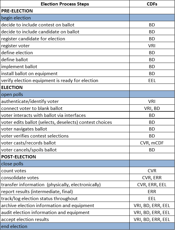
Figure 3 — Election process view of CDFs, processes, and interactions
A global election process view of CDFs, their processes, and respective interactions is shown in Figure 3 and described in more detail below. The ballot definition CDF plays a central role throughout a given election system. So, this system-level view is provided with respect to this context.
Election Management System Export. The Election Management System (EMS) is generally used to define the structure of ballots. This includes inputting contests and candidates that will appear on the ballot, organizing them in a logical order, and adding the necessary design elements. By using the BD CDF, the EMS can generate consistent and accurate ballot definitions that can be utilized by various components of the voting system.
Electronic Poll Books. Electronic Poll Books use ballot definitions to determine and issue the correct ballot to each voter based on their registration data. This includes verifying the voter's precinct, party affiliation, and any specific requirements such as language or accessibility needs. The correlation of precinct / split identifiers from the EPB to associated ballot styles in the BD ensures that the EPB can accurately match voters with the appropriate ballot, reducing the risk of errors and ensuring a smooth voting process.
Ballot Generation and Printing. Ballot definitions are instrumental in the generation of both electronic and paper ballots. They provide the necessary layout and structural data required to print ballots accurately. Additionally, ballot definitions ensure that the printed ballot matches the voter's eligibility and preferences. This is crucial for jurisdictions that offer different ballot styles based on precinct, party affiliation, or language preferences.
Vote capture and tabulation. In the vote capture and tabulation process, scanners and other vote capture devices use the layout information provided by the ballot definition to read and tally votes correctly. This includes interpreting marks on paper ballots or reading barcodes and other machine-readable elements on ballot selection records produced during ballot generation.
Ballot definition. Standardizing ballot styles facilitates interoperability between different voting system components and manufacturers. This is particularly important in jurisdictions that use equipment from multiple manufacturers. A common data format for ballot styles ensures that all components, from ballot printers to scanners and tabulation systems, can communicate effectively, reducing the risk of misinterpretation and aiding in accurate vote counting.
The BD CDF provides robust support for logical ballot definition and partial support for physical ballot definition in the form of contest selection capture. A full set of use cases for ballot styles is given in the white paper "Recommendations for Voting System Interoperability" [6], which provides a roadmap for future development in this area.
2.2 Cast Vote Records
Cast Vote Records provide digital representations of voted ballots.
The CVR CDF supports efficient tabulation of ballots, particularly for ballots containing rank choice voting contests.
It also enables the use of ballot-level comparison audits, which are an efficient approach to risk limiting audits. Risk limiting audits provide approaches to statistically verify the accuracy of election results [22].
Use of the CVR CDF enables public analysis of fine-grained voting data. Researchers can analyze voting patterns, such as ticket splitting and support for various candidates or issues, providing insights that can inform future electoral reforms and policies [8]. The availability of detailed voting data allows for a more comprehensive analysis than aggregate vote totals. While public analysis promotes transparency, it also necessitates careful consideration of voter privacy.
The VVSG 2.0 requires that vote-capture devices, Election Management Systems (EMSs) and other devices be capable of importing and exporting CVRs.
The term "cast vote records" is sometimes used interchangeably with "ballot images", however these are two separate but related, concepts. In the CVR CDF, ballot images can be referenced or embedded alongside the structured representations of the cast ballot.
Figure 4 illustrates an example workflow of ballot processing and result tabulation, divided into several distinct stages.
Figure 4 — High level data flow diagram for Cast Vote Records
The process begins with the scanning of ballots. In this initial stage, each ballot is scanned and interpreted to produce a Cast Vote Record (CVR). At this point, the raw selections may be placed into a CVR CDF instance or the processing of business rules may occur immediately prior.
In that case, predefined business rules are applied to ballot selections according to the voting method and contest parameters. The business rules are sourced from the Election Management System (EMS) component, which provides the necessary parameters for interpreting the ballots correctly.
Ballots may be flagged for review at the scanning or interpretation phase, e.g., when a marginal mark is detected in the former, and if a contest is overvoted in the latter. In such cases, an adjudication process may come into play. During adjudication, flagged ballots are examined to resolve any issues and ensure that the voter's intent is accurately reflected. This may involve making adjustments or confirming contest selections. The adjudication process is overseen by adjudicators who are responsible for interpreting and resolving any discrepancies found in the flagged ballots.
Once the ballots have been scanned, rules applied, and adjudicated, if necessary, the next step is to tabulate the votes. In this stage, the system aggregates the interpreted and adjudicated ballots to produce the final vote totals. These election results are then compiled and forwarded to the reporting system for dissemination.
The CVR CDF supports efficient ballot-level comparison audits. This step supports the integrity of the election results by cross-verifying a sample of ballots against the recorded data. Auditors conduct this verification process and interpret the audit results to confirm the reliability of the election outcome.
2.3 Elections Event Logging
The Election Event Logging (EEL) CDF is a standardized data format designed to facilitate the efficient and accurate exchange of election log data. It aims to improve the transparency, interoperability, and integrity of such logs.
Standardized event logging ensures the consistent reporting of election events across different devices and even jurisdictions, making it easier to aggregate and compare data.
EEL supports several approaches to logging:
Decentralized Logging. Each device maintains its own log, capturing all events specific to its operation. This decentralizes the logging process, allowing for detailed tracking of events on a per-device basis.
Combined Logging. Logs are combined into a Security Information and Event Management (SIEM) system. This centralization ensures that all logs are accessible from a single repository for analysis and auditing. Because logs are always correlated to the logging device, it is always possible to combine logs without losing context.
For a detailed treatment of EEL use cases, refer to the specification.
2.4 Election Results Reporting
The Election Results Reporting (ERR) specification provides a detailed and flexible common data format for pre-election setup information and election night, and post-election results reporting.
Pre-Election Use Case. The pre-election use case focuses on reporting various types of election-related data prior to the actual election day. Election officials use this use case to ensure the accuracy and organization of election data and to inform the public about upcoming elections. The data can be sourced from various systems such as voter registration databases, ballot programming systems, and campaign finance systems. Reports can be produced in multiple formats, including complete files, sequences of files, or as updates and corrections to previous reports. Pre-election reporting data includes jurisdictional information, political party details, candidate and officeholder information, election dates and types, ballot measures, contest details, and specific voting locations and devices.
Election Night Reporting. The election night reporting use case pertains to the real-time reporting of individual or aggregated election results. This use case supports the dissemination of election results to the public and media immediately following the close of polls. Depending on the jurisdiction's capabilities, detailed reporting at the precinct level may also be included. Results are typically reported either directly from local jurisdictions to the public/media or through an upward reporting process to state authorities. The data that may be reported includes contest-level results, votes for each candidate or selection, overvotes, undervotes, and breakdowns by precinct, ballot type, and device type. The aim is to provide timely and accurate election results, although these are considered unofficial until finalized.
Post-Election Reporting. The post-election reporting use case deals with the comprehensive reporting of final election results after all ballots have been counted and verified. This phase includes detailed breakdowns of vote counts by different types of ballots (e.g., absentee, provisional) and voting devices. Post-election reporting includes data that may not have been available on election night, such as late-arriving absentee ballots and provisional ballots. This detailed reporting is critical for analysts and media for in-depth election analysis, including voter behavior patterns and rejection rates for provisional ballots. The data reported includes all information from pre-election and election night reporting, as well as additional details on vote counts and summaries at various geographical and organizational levels.
2.5 microCDF
microCDF (mCDF) functions as a serialization format, supporting representation of complex data models in environments with limited storage capacities, such as on paper or in QR Codes. Serialization in this context involves transforming data into a format that is easy to store and reconstruct. mCDF achieves compactness by employing delimiters instead of tags and using default values to further reduce required storage space. Fields and segments in mCDF messages are separated by specific delimiters, while maintaining a hierarchical structure that reflects the relationships and nesting found in each profile's UML model.
The mCDF specification does not define data structures but rather a method for encoding data according to the profiles. Each profile serves as a template, specifying the data structures, types, and constraints necessary for specific use cases, such as the exchange of contest option selections or ballot style identifier information.
The following use cases are anticipated by the mCDF format:
Exchange of Activation Information. The mCDF can be used to support the exchange of activation information between ballot activation devices and ballot marking devices.
Exchange of Contest Option Selections. In the context of exchanging contest option selections between ballot marking devices and ballot scanners, mCDF offers a standardized method for transmitting voter selections. The Contest Selection Capture (CSC) message included in a future revision to CVR CDF provides support for this use case.
Exchange of Ballot Style Identifier Information. The mCDF supports storing specific identifiers on paper ballots, allowing scanners to correctly interpret and process different ballot styles. Appendix A of the Ballot Definition (BD) specification provides a detailed mCDF profile for Ballot Style Identification.
General Software-Independent Information Exchange. mCDF is designed for any application that requires software-independent information exchange, such as those involving paper-based data transfer. In these scenarios, mCDF facilitates the transfer of election data by leveraging its compact and flexible syntax.
By facilitating these specific types of data exchanges, mCDF enhances interoperability among election devices, which can lead to more componentized and flexible election systems, providing jurisdictions with greater choice and better integration capabilities.
Note: No further treatment of microCDF is given in this document.
2.6 Voter Records Interchange
The Voter Records Interchange (VRI) supports voter registration modernization efforts by providing a standardized format for exchange between voter registration databases (VRDBs) and other systems and agencies. This includes support for Online Voter Registration (OVR), Automatic Voter Registration (AVR) and National Voter Registration Act (NVRA) agency automation.
The VRI provides robust support for both the EAC's National Voter Registration Act (NVRA) and FVAP's Federal Post Card Application (FPCA) forms. This capability is particularly beneficial for states that have adopted these standardized forms for voter registration, as it facilitates a streamlined and efficient registration process.
In addition to its federal form support, the format offers native support for common state-specific requirements. VRI also includes functionality for handling various assertions that may be required by state laws. For example, it can process declarations regarding an individual's status as a member of the military or a citizen residing overseas.
When voters change their address, name, or other personal information, the use of VRI helps ensure that these updates are transmitted and recorded in a uniform manner. This reduces the likelihood of discrepancies and helps maintain the integrity of voter data across different systems.
2.6.1 Online Voter Registration Portals
Figure 5 provides a detailed representation of the flow of voter registration data from applicants to a voter registration database, demonstrating the different channels through which this data can be processed and integrated. It highlights the use of VRI CDF as the standard exchange format for this data.
Figure 5 — High level data flow diagram for Voter Records Interchange
The primary source of data in this example is the applicants agent block, representing individuals applying to register to vote. The diagram outlines three distinct pathways for the voter data to travel from applicants to the voter registration database.
The first pathway involves a State OVR system, which is managed by the election jurisdiction. In this scenario, voter data collected from applicants can be directly processed by the state-run OVR system or passed to the Registration Gateway.
The second pathway, labeled Third Party OVR, depicts the process when a third-party entity, such as a non-profit, operates their own OVR system. Voter data from applicants is collected by this third-party system and transmitted to the Registration Gateway using VRI CDF. This standardized format ensures consistent and accurate data exchange between the third-party OVR system and the election jurisdiction's registration gateway.
The third pathway involves an NVRA Agency. This governmental OVR system facilitates data exchange between the Department of Motor Vehicles (DMV) or similar systems and the voter registration systems. This pathway is crucial for digital notification of voter registration requests made by DMV customers. Additionally, it supports the semi-automated steps toward permanent voter registration by including updates from DMV records, such as change-of-address notifications (i.e. Automatic Voter Registration). This exchange of data, also in the VRI Common Data Format, ensures that all relevant voter information is efficiently communicated to the voter registration systems.
At the center of the data integration process is the Registration Gateway, a service endpoint provided by the election jurisdiction. The gateway accepts voter registration data from various sources, including OVR systems and NVRA agencies. It processes and validates this data, ensuring it is accurately formatted and ready for entry into the voter registration database.
Finally, the Voter Registration DB serves as the repository for all processed voter registration data. It receives data directly from the State OVR and through the Registration Gateway from third-party OVR systems and NVRA agencies. Additionally, the database provides eligibility responses, confirming the status of the voter registration applicants.
2.6.2 Voter Records Lookup
Figure 6 represents a workflow for handling requests for information regarding voter records within a Voter Registration (VR) system, or between a VR system and a third party.
Figure 6 — Eligibility determination data flow diagram for Voter Records Interchange
The process begins with requests for information about voter records. These requests might include prequalification inquiries for updating voter registration, for looking up voter registration status, or requests for general voter registration data exports.
In the prequalification of a voter scenario, the VR system is queried to determine whether a voter meets the criteria for updating their registration. This might involve verifying the voter's current registration status, checking for any outstanding issues, and ensuring compliance with the relevant rules and regulations.
For voter registration lookup applications, the system provides tools for users to check their registration status. This might include verifying whether they are registered to vote, confirming the details of their registration, and determining if their information is up to date.
2.6.3 Exports
The process also includes handling general voter registration exports, where large datasets of voter registration information are exported from the VR system. These data dumps might be requested by authorized entities for various purposes, such as analysis, auditing, or reporting. Ensuring the security, accuracy, and voter privacy when performing data dumps is crucial to maintaining the integrity of voter information.
2.7 Use Case Gaps
While CDFs described so far support numerous use cases, gaps remain in their ability to handle specific interoperability scenarios. An analysis of several known gaps was conducted by NIST in 2022 resulting in two documents, one evaluating interoperability needs outside the voting system [5] and another evaluating needs within it [6]. This section summarizes those documents.
Ballot Definition.
The Ballot Definition (BD) CDF was released in 2023 in response to a gap analysis paper. The primary objective of the BD CDF was to ensure full coverage of logical ballot styles and enhance the ability to capture vote selections from various types of ballots. This release represented a significant step forward in addressing interoperability issues within voting systems by standardizing the way ballot styles may be defined and vote selections may be recorded.
One major use-case that remains unaddressed is the ability to comprehensively describe ballot layouts for various ballot formats. The current specification does not provide sufficient detail to enable the generation of legally compliant ballots directly from the definition. Specifically, the BD CDF does not support the conveyance of typography information, certain design elements or their spatial arrangement.
Electronic Poll Books
Electronic Poll Books (EPB) face interoperability issues primarily in determining voter eligibility, issuing ballots, and tracking ballots. The VRI CDF supports several EPB functions, such as voter registration and querying voter records, but lacks optimization for EPB-specific scenarios. Additionally, the interoperability between EPBs and ballot activation systems is hindered due to the absence of a standardized ballot activation data format. Recommendations include extending the VRI to better support EPB use cases, developing an EPB-specific CDF, and creating a Ballot Activation CDF to facilitate seamless interaction between EPBs and ballot marking devices.
Interactions between Electronic Poll Books and Voter Registration Databases (VRDBs)
Interactions between EPBs and VRDBs require detailed information structures to support various functions such as ballot tracking, voter registration, and voter eligibility determination. Current data formats partially support these interactions, but gaps exist in conveying detailed ballot and voter information. Enhancing the VRI to explicitly cover these data flows and developing interoperable data formats for ballot tracking and voter registration details are necessary to improve interoperability between EPBs and VRDBs.
On-Demand Ballot Printing
The On-Demand Ballot Printing (ODBP) systems face several interoperability
challenges primarily related to ballot style determination, ballot printing,
and ballot tracking. The existing Voter Records Interchange (VRI) Common
Data Format only provides partial support for determining ballot styles
through
ReportingUnit
identifiers, but lacks the capability to convey detailed presentation data
required for printing ballots. Additionally, VRI does not adequately support
the tracking of ballot sequence numbers, which is critical for maintaining
the chain of custody and ensuring auditability. Recommendations include
extending the VRI specification to better support on-demand ballot printing
scenarios and developing a dedicated ballot style CDF to address the
deficiencies in conveying ballot presentation data.
Remote Ballot Marking
Remote Ballot Marking (RBM) systems encounter gaps in voter authentication, ballot style determination, ballot generation, and ballot transcription. While the VRI CDF supports voter authentication and eligibility determination, it falls short in providing detailed ballot style data necessary for generating markable ballots. Enhancing the VRI to explicitly cover remote ballot marking use cases and incorporating support for high fidelity ballot styles within the Ballot Definition CDF is recommended. Additionally, addressing the electronic return of ballots in a privacy-preserving manner is crucial.
2.8 Finding Common Data Format Resources
The first place to go when looking for CDF Resources is the NIST Voting Program website, accessible at https://www.nist.gov/itl/voting. The Interoperability page provides up to date, official publications from NIST.
NIST Voting Common Data Formats are published as NIST Technical Series Publications. NIST Technical Special Publication (SP) Series 1500 has been used for all CDFs developed so far. Each publication is commonly referred to as a "CDF Specification". Each NIST publication is given a Publication ID (PubID) of the form {series} {report number} {edition} {update} {update number} {update year}. Table 3 provides a listing of the published CDFs at time of writing, associated PubID and document object identifiers.
Table 3. Listing of common data formats and associated identifiers
|
Common Data Format |
PubID |
DOI |
|
Micro Common Data Format Specification Version 1.0 |
SP 1500-19 |
10.6028/NIST.SP.1500-19 |
|
Ballot Definition Common Data Format Specification Version 1.0 |
SP 1500-20 |
10.6028/NIST.SP.1500-20 |
|
Election Results Common Data Format Specification Revision 2.0 |
SP 1500-100r2 |
10.6028/NIST.SP.1500-100r2 |
|
Election Event Logging Common Data Format Specification Version 1.0 |
SP 1500-101 |
10.6028/NIST.SP.1500-101 |
|
Voter Records Interchange Common Data Format Specification Version 1.0 |
SP 1500-102 |
10.6028/NIST.SP.1500-102 |
|
Cast Vote Records Common Data Format Specification Version 1.0 |
SP 1500-103 |
10.6028/NIST.SP.1500-103 |
All CDF specifications are assigned Document Object Identifiers (DOIs) [2]. DOIs provide permanent links that will always lead to the current location of each publication, even if the original URL changes. This ensures long-term accessibility and reliability for citing NIST publications.
NIST Voting Common Data Formats are published according to the Common Data Format lifecycle policy [7].
3 Understanding Common Data Formats from the UML Model
The development of the NIST 1500 series Common Data Formats (CDFs) follows a Model Driven Architecture (MDA) approach. This means that a high-level representation (i.e., model) of each common data format is developed, and then transformed into implementation formats that can be used by developers. This model is specified using the standardized syntax of the Unified Modeling Language (UML) [1]. The relationship between layers of representation is given in Figure 7.
Figure 7 — Common data format artifacts
All CDFs are documented in terms of the model; therefore, understanding of the UML class model and how it maps to the JSON [11] and XML [10] is required for implementers.
This section provides background regarding how the NIST 1500 UML models map into the implementation formats.
Examples used throughout this document are based on a subset of the Election Results Reporting specification, v2.0 [12]. Examples may abbreviate the actual definitions used in XSD or JSON Schema in order to emphasize a particular concept.
This section is not intended to be an introduction to UML, JSON or XML.
3.1 Types
Every property in the UML model belongs to a particular type, which has the
effect of constraining the range of values allowed for that property. For UML
attributes, types are indicated after the colon in the attribute listing. For
associations, the UML type is indicated by the target of the relationship, i.e.,
the class pointed to by the arrow. In Figure
8,
Contest::Name's type is
String, while
Contest::ElectionDistrict's type is
ReportingUnit.
Figure 8 — Two classes showing their types
3.1.1 Data Types
From Figure 8, it is clear where the
type
ReportingUnit comes from,
ReportingUnit is a class defined
in the model. However, where does the UML type String come from?
String is a built-in UML primitive
type. Primitive types are used to represent atomic values. The UML provides
5 different primitive types:
-
Boolean -
Integer -
Real -
String -
UnlimitedNatural
XML maps UML Primitive types to either an XML element typed as Parsed Character Data (PCDATA, default) or an XML attribute (controlled by stereotypes, see Section 3.5).
JSON distinguishes between objects (which are collections of key-value pairs)
and primitive values (which are individual data items like
strings,
numbers, and
booleans). Primitive types in UML map directly to these
non-object JSON values.
The primitives provided by UML are limited in comparison to other languages. However, UML allows for the creation of additional, custom data types. The CDFs extend the UML set of primitive types with that of the XSD's to augment the UML types available.
Presented in Figure 9 is the hierarchy of XSD built-in primitive and derived primitive types that are used in various CDFs. The data types in bold are used by a CDF, those in blue are extended types defined in one or more CDFs, and those in gray are not used directly, but are an ancestor of a used data type and constrains the data in some way.
The use of inherited constraints from ancestor types, even those not directly utilized, ensures that all derived types conform to a foundational set of rules. For more information see Section 3.1.1.1.
Figure 9 — Data type hierarchy
Because the UML models use the XSD types directly, the mapping from a CDF's UML model to an XSD schema is straightforward. However, for the JSON Schema these XML data types must be mapped to their equivalents, given in Table 4.
Table 4. Listing of UML/XSD types and JSON equivalents
|
UML |
JSON |
JSON Format |
|
|
|
|
|
|
|
|
|
|
|
|
|
|
|
|
|
|
|
|
|
|
|
|
|
|
|
|
|
|
|
|
|
|
|
|
|
|
|
|
|
|
|
|
|
|
|
|
|
|
|
|
|
|
|
|
JSON Schema uses JSON Formats to further constrain the basic JSON data types. These formats are often related to specific types of data commonly encountered in applications, such as dates, times, URIs, email addresses, and more.
Handling of
xsd:ID,
xsd:IDREF and
xsd:IDREFs is given in Section 4.1. Handling for
xsd:language is given in Section 6.4.
3.1.1.1 Extended Data Types
The UML primitive types can be further extended by creating new data types based on them. When a data type is extended, it inherits all the constraints and facets of its base type, with additional restrictions potentially being imposed to narrow the scope of acceptable values. This inheritance of constraints ensures that derived types maintain the identity and validation rules of their ancestors while providing more specific constraints tailored to particular use cases.
Note: Extension of UML primitives is an action reserved exclusively to the authors of the CDFs. End-users of the specifications should not extend the CDFs if they wish to be conformant with published specification (see Section 6.7).
For example, if a CDF uses an extended type derived from a built-in XSD
type like
xsd:string, the
extended type may introduce restrictions such as a specific pattern,
length constraints, among others. These additional constraints are
layered on top of the inherent facets of string, ensuring that any
instance of the extended type adheres to both the base type's rules
and the newly defined restrictions. Figure 10 shows
ShortString inheriting from
xsd:string and setting the property
maxLength to 32.
Figure 10 — ShortString extending the XSD string primitive type
This maxLength constraint in Figure 10 corresponds to a facet in
the XSD model. The equivalent XSD and JSON Schema structures are given
in Figure 11 and Figure 12.
<xsd:simpleType name="ShortString">
	<xsd:restriction base="xsd:string">
		<xsd:maxLength value="32"/>
	</xsd:restriction>
</xsd:simpleType>
Figure 11 — ShortString definition in XSD
{
	"ElectionResults.ShortString": {
		"type": "string",
		"maxLength": 32
	}
}
Figure 12 — ShortString definition in JSON Schema
3.1.1.2 Enumerations
An enumeration is a data type that restricts the possible values to a set
of named literals. An example using
IdentifierType is shown in Figure 13.
IdentifierType is used with
ExternalIdentifier, further discussed in Section 4.3.
Figure 13 — IdentifierType with several defined literals
UML Enumerations become
simpleTypes in XML which restrict a string value to the
enumeration values defined, as shown in Figure 14.
<xsd:simpleType name="IdentifierType">
	<xsd:restriction base="xsd:string">
		<xsd:enumeration value="fips"/>
		<xsd:enumeration value="local-level"/>
		<xsd:enumeration value="national-level"/>
		<xsd:enumeration value="ocd-id"/>
		<xsd:enumeration value="state-level"/>
		<xsd:enumeration value="other"/>
	</xsd:restriction>
</xsd:simpleType>
Figure 14 — IdentifierType definition in XSD
Likewise, UML Enumerations become JSON
string types with the enum constraint set
in JSON Schema, as given in Figure
15.
"ElectionResults.IdentifierType": {
	"type": "string",
	"enum": [
		"fips",
		"local-level",
		"national-level",
		"ocd-id",
		"other",
		"state-level"
	]
}
Figure 15 — IdentifierType definition in JSON Schema
3.1.2 Classes
A class defines the set of objects sharing the same features and constraints. In the CDFs, classes provide blueprints for represent real world objects such as candidates, contests, parties among others.
3.1.2.1 Abstract Classes
There are some classes that cannot be instantiated directly. These
abstract classes serve as a template for
creating subclasses that can be used directly by implementers. The
subclasses inherit all the defined properties of the abstract parent.
Figure 16 shows
CandidateContest inheriting from
Contest.
Figure 16 — CandidateContest inheriting from abstract class Contest
Logically, this is equivalent to the properties (including associations)
being directly included in
CandidateContest as shown in Figure 17.
Figure 17 — A logical view of CandidateContest with all properties from Contest inherited
When encountering a class that references an abstract class, as shown in Figure 18, the implementer must choose the proper subtype they wish to use.
Figure 18 — Election composing abstract class Contest
The
xsi:type attribute is used
in XML Schema instances (XSI) to explicitly specify the actual type of
an element when it is instantiated from an abstract class defined in an
XML Schema (XSD) or if a more specific subtype is called for generally.
The use of
xsi:type to
specify the subtype
CandidateContest is given in Figure 19.
<ElectionReport xmlns="http://itl.nist.gov/ns/voting/1500-100/v2" xmlns:xsi="http://www.w3.org/2001/XMLSchema-instance">
	...
	<Contest xsi:type="CandidateContest" ObjectId="cc-1">
		…
	</Contest>
	...
</ElectionReport>
Figure 19 — Usage of a concrete class in XML
While the namespace URI for XSI (https://www.w3.org/2001/XMLSchema-instance) is fixed, the
prefix (such as
xsi in this
case) can be chosen by the user. The option exists to declare it as
something else like
myxsi as
long as there is consistent use of that prefix throughout the document
to associate it with the same namespace URI.
However, using a standard prefix like
xsi enhances readability and ensures broader
compatibility with XML processors that understand common
conventions.
If the concrete type has a namespace prefix declared in the document,
then the
xsi:type value
should include that prefix as shown in Figure 20.
<cdf:ElectionReport xmlns:cdf="http://itl.nist.gov/ns/voting/1500-100/v2" xmlns:xsi="http://www.w3.org/2001/XMLSchema-instance">
	...
	<cdf:Contest xsi:type="cdf:BallotMeasureContest" ObjectId="bmc-1">
		...
	</cdf:Contest>
	...
</cdf:ElectionReport>
Figure 20 — Usage of a concrete class with namespace prefix in XML
In JSON, the correct type is chosen by using the
@type key, as demonstrated in Figure 21.
{
	"@type": "ElectionResults.CandidateContest",
	...
}
Figure 21 — Usage of a concrete class in JSON
The @type value consists of two parts: the UML Package name and the UML class name, separated by a period. The UML Package names are not documented in the CDF specifications and are thus provided in Table 5 for convenience.
Table 5. UML Package Names for each Common Data Format
|
Common Data Format |
UML Package Name |
|
Ballot Definition Common Data Format Specification |
|
|
Cast Vote Records Common Data Format Specification version 1.0 |
|
|
Election Event Logging Common Data Format Specification |
|
|
Election Results Common Data Format Specification revision 2.0 |
|
|
Voter Records Interchange Common Data Format Specification version 1.0 |
|
3.2 Root Element
The UML class model is a graph data structure in the sense that there is no
hierarchy implied by the model. However, the two supported implementation
formats, JSON and XML, are hierarchical in structure (also called a tree). All
hierarchies must start with a root, which is indicated in the UML model as a
class with the
«root» stereotype
applied. In Figure 22 the
ElectionReport class will be generated in XML
Schema as the root element
ElectionReport.
Figure 22 — ElectionReport with Root stereotype
A single model can have multiple root elements. For example, VRI has two root
elements, one
VoterRecordsRequest for
making requests, and
VoterRecordsResponse for receiving responses. Likewise, EEL has
ElectionEventLog for producing log
files containing event described by types and identifiers and
ElectionEventLogDocumentation for describing the
meaning of those event types and identifiers.
3.3 Relationships Between Classes
The major classes in the UML model result in major elements in the schemas, and the different types of relationships between the UML classes determine how the elements are structured (linked) in the schema. There are three types of relationships between the classes:
Directed Composition. In Figure
23,
ElectionReport and
Election should be read as, "An
election report is composed of elections." In the XML schema for example, the
Election element will be generated as
a sub-element of the
ElectionReport
element. A directed composition relationship has a closed diamond at one end and
an arrow pointing to the composing class.
Figure 23 — Directed Composition Example
The equivalent representation in XSD is given in Figure 24.
<xsd:complexType name="ElectionReport">
	<xsd:sequence>
		<xsd:element name="Election" type="Election" minOccurs="0"  maxOccurs="unbounded">
		</xsd:element>
	</xsd:sequence>
</xsd:complexType>
Figure 24 — Directed composition using XSD
The equivalent representation in JSON Schema is given in Figure 25.
"ElectionResults.ElectionReport": {
	...
	"type": "object",
	"properties": {
		"Election": {
			"type": "array",
			"minItems": 0,
			"items": {
				"$ref": "#/definitions/ElectionResults.Election"
			}
		}
		...
	}
}
Figure 25 — Directed composition using JSON Schema
Is a Type of (Generalization). In Figure 26, Contest and CandidateContest should be read as, "A candidate
contest is a type of contest." Contest is an abstract class (indicated by
placing the class name in italic font); it is "implemented" by its concrete
classes such as CandidateContest. In the XML schema, Contest will be generated
as an abstract type and serves as an extension base to the
CandidateContest element. A generalization
relationship has an open triangle at one end, pointing from the concrete class
to the abstract class.
Figure 26 — "Is a Type of" Example
The equivalent representation in XSD is given in Figure 27.
<xsd:complexType name="CandidateContest">
	<xsd:complexContent>
		<xsd:extension base="Contest">
			<xsd:sequence>
				...
			</xsd:sequence>
		</xsd:extension>
	</xsd:complexContent>
</xsd:complexType>
Figure 27 — "Is a Type of" using XSD
JSON Schema does not support object-oriented constructs. Instead, each concrete class is defined with its own properties, including all properties inherited by its parents. When a type with descendants is specified, the schema generation tool uses the oneOf construct, which allows one of the concrete children to be selected, as shown in Figure 28.
"Contest": {
	...
	"items": {
		"oneOf": [
			{
				"$ref": "#/definitions/ElectionResults.PartyContest"
			},
			{
				"$ref": "#/definitions/ElectionResults.BallotMeasureContest"
			},
			{
				"$ref": "#/definitions/ElectionResults.CandidateContest"
			},
			{
				"$ref": "#/definitions/ElectionResults.RetentionContest"
			}
		]
	}
}
Figure 28 — Use of JSON Schema "oneOf" keyword
Directed Association: In Figure
29, Contest and Reporting, should be read as, "A contest is associated
with or linked to a reporting unit." In the XML schema, the
Contest element will include a
ElectionDistrictId element (based on the role name,
see Section 4.1), which will contain
an identifier associated with a
ReportingUnit element. A directed association has an arrow at
one end, goes in one direction, and serves to link the class to another
associated class, e.g., the reporting unit linked to the contest.
Figure 29 — Directed Association Example
The equivalent in XSD is given in Figure
30. Because JSON does not support inheritance the JSON example in Figure 31 uses
CandidateContest instead of
Contest.
<xsd:complexType name="Contest" abstract="true">
	<xsd:sequence>
		...
		<xsd:element name="ElectionDistrictId" type="xsd:IDREF"/>
		...
	</xsd:sequence>
	<xsd:attribute name="ObjectId" type="xsd:ID" use="required"/>
</xsd:complexType>
Figure 30 — Contest definition in XSD
"ElectionResults.CandidateContest": {
	"type": "object",
	"properties": {
		"@id": {
			"type": "string"
		},
		...
		"ElectionDistrictId": {
			"type": "string"
		}
		...
	}
	...
}
Figure 31 — CandidateContest definition in JSON Schema
3.4 Terminology Mapping
Terminology can be difficult because JSON, UML, and XML were all developed independently and use different terms to represent similar concepts. An attempt at mapping these concepts is described in Table 6.
Table 6. Mapping of terminology
|
UML |
XML Schema |
JSON Schema |
|
Class |
|
|
|
Property |
|
|
|
Enumeration |
|
|
|
Supertype |
|
|
|
Multiplicity |
|
|
|
Cardinality |
|
|
UML uses the term property to refer to either an attribute or an association.
A glossary of terms is available in Appendix A.
3.5 Elements and Attributes
In the UML model, the classes become
complexTypes in the XML schema. The attributes of a class
become XML sub-elements of the
complexTypes.
JSON (as with UML) only provides a single data structure for presenting
information, in JSON these are called objects, whereas XML provides two data
structures for presenting data, elements and attributes. If a UML attribute has
the
«xmlAttribute» stereotype or
the class contains an attribute with the
«simpleContent» stereotype as shown in Figure 32, then XML attributes are generated. The
«simpleContent» stereotype
indicates that the UML attribute is the target for the character data of the XML
element. For example, the following UML represents a class named FileValue with
two XML attributes:
Figure 32 — Class with attribute using «simpleContent» stereotype
An example using XML is:
<FileValue FileName="String"
MimeType="string">UjBsR09EbGhjZ0dTQUxNQUFBUUNBRU1tQ1p0dU1GUXhEUzhi</FileValue>
3.6 Representing Multiplicities
Some properties in the UML model can repeat. Repetition is represented by multiplicities whose lower or upper cardinality is greater than one, e.g., 1..2, 2..4, 0..*, etc. An asterisk (*) for the upper cardinality represents an unbounded number of repetitions. A "1" for the lower cardinality indicates that the attribute is required.
UML attributes with multiplicities greater than one are represented in XML as repeating elements, as shown in Figure 33.
<Uri Annotation="mobile">http://mobile.samplesite.com/</Uri>
<Uri Annotation="desktop">http://www.samplesite.com/</Uri>
Figure 33 — Uri repeating using XML
In JSON, UML attributes with multiplicities greater than one are represented as an array of objects, as shown in Figure 34.
"Uri":
    [
        {
            "@type": "ElectionResults.AnnotatedUri",
            "Annotation": "mobile",
            "Content": "http://mobile.samplesite.com/"
        },
        {
            "@type": "ElectionResults.AnnotatedUri",
            "Annotation": "desktop",
            "Content": "http://www.samplesite.com/"
        }
    ]
Figure 34 — Uri repeating using JSON
Even if an implementer wants to provide a single occurrence of an attribute, it must be wrapped in an array, as shown in Figure 35.
"Uri":
    [
        {
            "@type": "ElectionResults.AnnotatedUri",
            "Annotation": "mobile",
            "Content": "http://mobile.samplesite.com/"
        }
    ]
Figure 35 — Single value for array typed property in JSON
3.7 References
Some classes of data may be referenced repeatedly, for example political parties or geopolitical units. It would make sense to define single instances of these classes and then reference them whenever they are needed as opposed to creating new instances. The UML model represents these references as directed associations between classes. Figure 36 shows a reusable ReportingUnit that is referenced by multiple Contests.
Figure 36 — UML Instance using references
In this figure, two contests are defined; they are of type
CandidateContest and both have the same election
district: Summit County. Only one reporting unit for Summit County needs to be
defined, however, because the contests can reference the reporting unit as
needed.
The XML representing the classes in Figure 36 is given in Figure 37 - Reusable data using XML.
<ElectionReport>
	<Election>
		<Contest ObjectId="cc-sc-sherif" xsi:type="CandidateContest">
			<ElectionDistrictId>gp-summit-county</ElectionDistrictId>
			<Name>Summit County Sheriff</Name>
		</Contest>
		<Contest ObjectId="cc-sc-fiscal-officer"
             xsi:type="CandidateContest">
			<ElectionDistrictId>gp-summit-county</ElectionDistrictId>
			<Name>Summit County Fiscal Officer</Name>
		</Contest>
		<ElectionScopeId>gp-summit-county</ElectionScopeId>
		<Type>general</Type>
	</Election>
	<GpUnit ObjectId="gp-summit-county">
		<Name>Summit County</Name>
	</GpUnit>
</ElectionReport>
Figure 37 — Reusable data using XML
XML provides two built in types for handling references: one for establishing the
reusable element (
xsd:ID) and one for
referencing it (
xsd:IDREF).
Identifiers are defined using the
ObjectId attribute. The name of the identifier must be unique
across the XML instance and conform to restrictions specified by the
xsd:NCName datatype. An
xsd:NCName
value must start with either a letter or underscore and may
contain only letters, digits, underscores, hyphens, and periods.
JSON references are handled by the use of an
@id property as given in Figure 38 - Reusable data using JSON.
{
	"@type": "ElectionResults.ElectionReport",
	"Election": [
		{
			"@type": "ElectionResults.Election",
			"Contest": [
				{
					"@id": "cc-sc-sheriff",
					"@type": "ElectionResults.CandidateContest",
					"ElectionDistrict": "gp-summit-county",
					"Name": "Summit County Sheriff"
				},
				{
					"@id": "cc-sc-fiscal-officer",
					"@type": "ElectionResults.CandidateContest",
					"ElectionDistrict": "gp-summit-county",
					"Name": "Summit County Fiscal Officer"
				}
			],
			"Type": "general"
		}
	],
	"GpUnit": [
		{
			"@id": "gp-summit-county",
			"@type": "ElectionResults.ReportingUnit",
			"Name": "Summit County"
		}
	]
}
Figure 38 — Reusable data using JSON
4 Working with Identifiers
Identifiers are strings that serve as shorthand references to entities that may exist elsewhere. These could be other electronic data or real-world entities. In the context of electronic data, an identifier can reference a data element defined in the same document, an external document such as a ballot image, or any other discrete piece of information. Identifiers can also reference physical objects such as polling locations, geography, or individuals.
4.1 Document cross-references
Common Data Formats use cross-references extensively throughout. In the UML Model, classes can relate to other elements, including other classes. In a real-world example, a contest may be associated with exactly one reporting unit (i.e. its election district). The definition of a given reporting unit only needs to be described once no matter how many contests may be associated with it.
In order to reduce the size of CDF instance files and provide consistent data access, reusable data is defined once then referenced as often as needed. This referencing is accomplished through assigning a unique identifier to the referenceable object, then referring to that object using that identifier.
Object identifiers are defined using the
ObjectId attribute (in XML) or the
@id key (in JSON). In this section,
ObjectId is used to refer to both.
4.1.1 Usage and Restrictions
To be used,
ObjectIds must first
be defined in the schema. The schema generation tools used by NIST to build
the CDF schemas will produce them on an as-needed basis. That is, an
ObjectId will be generated only
for a class that is referenced by other classes' properties.
In Figure 39, class
C will be generated with an
ObjectId attribute as it is referenced by
another class,
B. B will not have an
ObjectId as no other class references it.
Figure 39 — Directed association between two classes
Conversely, B will have an element of type
IDREF named
CId
which links
B to
C, as given in Figure 40 - Example cross-reference using XSD.
<xsd:schema xmlns:xsd="http://www.w3.org/2001/XMLSchema"
xmlns="http://itl.nist.gov/ns/voting/1500-999/v1" elementFormDefault="qualified"
targetNamespace="http://itl.nist.gov/ns/voting/1500-999/v1" version="1.0">
	<xsd:element name="A" type="A"/>
	<xsd:complexType name="A">
		<xsd:sequence>
			<xsd:element name="B" type="B"/>
			<xsd:element name="C" type="C"/>
		</xsd:sequence>
	</xsd:complexType>
	<xsd:complexType name="B">
		<xsd:sequence>
			<xsd:element name="CId" type="xsd:IDREF"/>
		</xsd:sequence>
	</xsd:complexType>
	<xsd:complexType name="C">
		<xsd:attribute name="ObjectId" type="xsd:ID" use="required"/>
	</xsd:complexType>
</xsd:schema>
Figure 40 — Example cross-reference using XSD
In Figure 40, the element containing
the reference to
B is named
BId. In most cases, the name of
the element is implicitly constructed from the class name. However, if a
role name is given, then the role name is used instead.
Figure 41 revises the previous
example, where the association's end for
B is given the role name
RoleOfC.
Figure 41 — Directed associations between two classes with role names
Consequently
B will have an
element of type
IDREF named
RoleOfCId which links
B to
C, as shown in Figure
42.
<xsd:schema xmlns:xsd="http://www.w3.org/2001/XMLSchema"
xmlns="http://itl.nist.gov/ns/voting/1500-999/v1" elementFormDefault="qualified"
targetNamespace="http://itl.nist.gov/ns/voting/1500-999/v1" version="1.0">
	<xsd:element name="A" type="A"/>
	<xsd:complexType name="A">
		<xsd:sequence>
			<xsd:element name="B" type="B"/>
			<xsd:element name="C" type="C"/>
		</xsd:sequence>
	</xsd:complexType>
	<xsd:complexType name="B">
		<xsd:sequence>
			<xsd:element name="RoleOfCId" type="xsd:IDREF"/>
		</xsd:sequence>
	</xsd:complexType>
	<xsd:complexType name="C">
		<xsd:attribute name="ObjectId" type="xsd:ID" use="required"/>
	</xsd:complexType>
</xsd:schema>
Figure 42 — Example cross-reference with role name using XML
The allowed references to a given class are specified in the UML model. In some cases, a reference may be optional, while in others it may be required. Likewise, sometimes only a single reference can be specified, e.g., a candidate to a person, while in other cases, multiple references are allowed, such as from a geography to its composing geopolitical units.
In XML, single references are conveyed using the type
xsd:IDREF, and multiple references use the type
xsd:IDREFS. In Figure 43, the cardinality of
RoleOfC is changed from 1 to *, which has the
effect of allowing an unbounded number of references from
B to
C.
Figure 43 — Directed associated between two classes with RoleOfB multiplicity of 1..*
As such,
B will have an element of
type
IDREFS named
RoleOfCIds which links
B to
C, as presented in Figure
44.
<xsd:schema xmlns:xsd="http://www.w3.org/2001/XMLSchema"
xmlns="http://itl.nist.gov/ns/voting/1500-999/v1" elementFormDefault="qualified"
targetNamespace="http://itl.nist.gov/ns/voting/1500-999/v1" version="1.0">
	<xsd:element name="A" type="A"/>
	<xsd:complexType name="A">
		<xsd:sequence>
			<xsd:element name="B" type="B"/>
			<xsd:element name="C" type="C"/>
		</xsd:sequence>
	</xsd:complexType>
	<xsd:complexType name="B">
		<xsd:sequence>
			<xsd:element name="RoleOfCIds" type="xsd:IDREFS"/>
		</xsd:sequence>
	</xsd:complexType>
	<xsd:complexType name="C">
		<xsd:attribute name="ObjectId" type="xsd:ID" use="required"/>
	</xsd:complexType>
</xsd:schema>
Figure 44 — Example of directed association with unbounded upper cardinality using XML
A XML instance will use the element
RoleOfCIds to associate
B with elements of
C as shown in Figure
45.
<A xmlns="http://itl.nist.gov/ns/voting/1500-999/v1"
xmlns:xsi="http://www.w3.org/2001/XMLSchema-instance">
	<B>
		<RoleOfCIds>ID1</RoleOfCIds>
	</B>
	<C ObjectId="ID1"/>
</A>
Figure 45 — Example instance of directed associated with unbounded upper cardinality using XML
A JSON equivalent of the XSD is given in Figure 46.
{
  "$ref": "#/definitions/CDFModel.A",
  "$schema": "http://json-schema.org/draft-04/schema#",
  "definitions": {
    "CDFModel.A": {
      "required": [
        "@type",
        "B",
        "C"
      ],
      "additionalProperties": false,
      "properties": {
        "@type": {
          "enum": [
            "CDFModel.A"
          ],
          "type": "string"
        },
        "B": {
          "$ref": "#/definitions/CDFModel.B"
        },
        "C": {
          "$ref": "#/definitions/CDFModel.C"
        }
      },
      "type": "object"
    },
    "CDFModel.B": {
      "required": [
        "@type",
        "RoleOfCIds"
      ],
      "additionalProperties": false,
      "properties": {
        "@type": {
          "enum": [
            "CDFModel.B"
          ],
          "type": "string"
        },
        "RoleOfCIds": {
          "items": {
            "type": "string",
            "refTypes": [
              "CDFModel.C"
            ]
          },
          "minItems": 1,
          "type": "array"
        }
      },
      "type": "object"
    },
    "CDFModel.C": {
      "required": [
        "@id",
        "@type"
      ],
      "additionalProperties": false,
      "properties": {
        "@id": {
          "type": "string"
        },
        "@type": {
          "enum": [
            "CDFModel.C"
          ],
          "type": "string"
        }
      },
      "type": "object"
    }
  }
}
Figure 46 — Example of directed association with unbounded upper cardinality using JSON
ObjectIds have several naming and
usage restrictions. First, they must be globally unique within a given
instance file, i.e., no two objects can be identified by the same
ObjectId, even if those objects
are of different types (see Section
4.1.2 for a workaround). Secondly,
ObjectIds use the
xsd:ID data type, which restricts the characters that can
be used within them. Thirdly,
ObjectIds will only appear in a file if the class is
referenced elsewhere. Finally,
ObjectIds cannot be used to refer to objects outside the
instance's scope. For these reasons, we strongly recommend that
ObjectIds not be used to convey
durable identifiers, i.e., identifiers that will be stored in a destination
system. Instead, we recommend the use of
ExternalIdentifiers (see Section 4.3) for this purpose.
xsd:ID are a subtype of
xsd:NCName (see Figure 9) and therefore must begin with a letter or an
underscore, and subsequently consist of letters, digits, period, hyphen and
underscores. This conformance to this restriction can be validated using the
CDF Test Method (see Section
7.3).
4.1.2 Standardized Prefixes
As previously mentioned,
ObjectIds
must follow a number of naming restrictions. Over time, standardized
prefixes have developed. These prefixes clarify what the object is from its
name alone. It also reduces the chances that a generating system violates
the uniqueness constraints for object identifiers. By employing a systematic
approach to prefix usage, each category of objects can be managed within its
own "namespace." A set of standardized prefixes are specified in
Table 7.
Table 7. Standardized prefixes for object identifiers
|
Class |
Prefix |
|
ActivationContest |
|
|
ActivationOption |
|
|
BallotFormat |
|
|
BallotMeasureContest |
|
|
BallotMeasureOption |
|
|
BallotMeasureSelection |
|
|
Candidate |
|
|
CandidateContest |
|
|
CandidateOption |
|
|
CandidateSelection |
|
|
Coalition |
|
|
Contest |
N/A |
|
ContestOption |
N/A |
|
ContestSelection |
N/A |
|
ControllingContest |
|
|
CVRSnapshot |
|
|
Election |
|
|
GpUnit |
N/A |
|
Header |
|
|
Office |
|
|
Party |
|
|
PartyContest |
|
|
PartyOption |
|
|
PartyPreferenceContest |
|
|
PartySelection |
|
|
Person |
|
|
ReportingDevice |
|
|
ReportingUnit |
|
|
Shape |
|
|
StraightPartyContest |
|
4.2 Internal Code Lists
Data can be categorized based on different aspects. The class data belongs to
provides a broad categorization (e.g.,
CandidateContest vs.
BallotMeasureContest). More specific categorization can further
distinguish between "what something is" and "what it is
called". For instance, a
BallotMeasureContest (what it is) might have its
Type property set to "recall" (what it is
called) providing a more specific category beyond just the class. Setting this
Type property doesn't affect the
structure of the class itself.
Each CDF specification comes with several predefined enumerations, which can be used to categorize certain classes or data within them. Each enumeration contains a set of literals that represent what things are called in different jurisdictions, and thus implementers are free to use the categorization that makes the most sense within their local context.
Some enumerations have a literal
other
which may be used to indicate a custom literal will be provided. This should
only be used when no predefined literal reasonably applies to data being
categorized.
Code lists can be used to simplify data reporting. For example, the Voter Records Interchange (VRI) format is aligned with the standardized categories used by the Election Administration and Voting Survey (EAVS) Section A and Section B in terms of request method and military classification types. This facilitates immediate collection of relevant transactional data at a fine level of granularity, simplifying data collection for this survey. The enumerations used for this data collection are given in Figure 47.
Figure 47 — RequestMethod and VoterClassificationType can be used for EAVS Survey
4.3 External Identifiers
External Identifiers, also referred to as Codes by certain CDFs, are indented to convey durable references outside a given instance's scope.
ExternalIdentifiers were originally
designed to support the Election Results Reporting (ERR) CDF. One of the use
cases of ERR is data rollups between systems. For example, election results may
roll up from the local jurisdiction to the state, or even federal level.
ExternalIdentifiers can be used to
convey an identifier from one system to another such that data can be round
tripped.
A common scenario involves feeding candidate information, identifiers, and other ballot data from a state Election Management System (EMS) to a local EMS for the purpose of election programming. Once the election is conducted, the results are then fed back up to the state EMS. By using the state-defined identifiers, the data can be accurately correlated and reconciled.
The use of predefined literals such as local-level, state-level, and
national-level within
ExternalIdentifiers helps in indicating the scope and context
of these identifiers. This hierarchical coding system ensures that data can be
properly aggregated and disaggregated at various levels of election
management.
The second predefined External Identifier types are Open Civic Identifiers [13] (
ocd-id) and FIPS codes [14] (
fips). OCD-IDs are
designed to provide a single, unique identifier for geographies, particularly
political geography used in elections. FIPS codes on the other hand are
primarily used for legally defined geography such as states, counties or
municipal equivalents. Such codes provide a consistent way to classify
geographic areas and makes data analysis and comparison between different
jurisdictions easier.
Note: The correct FIPS standard to use for any given class is not defined in this document.
Finally, there are certainly identifier types not envisioned by the
specifications that nonetheless need to be conveyed using the External
Identifiers. In this case implementers can use the other option
available in every enumeration. When this enumeration literal is used, then a
value is expected in the corresponding
OtherType property.
4.4 Domain Specific Identifiers
There are identifiers that do not fall into any of the categories described thus far. These identifiers are domain specific and their usage is given by the description associated with each property. Examples include:
-
CVR::BallotAuditId -
CVR::BallotPrePrintedId -
CVR::BatchSequenceId -
CVR::BallotSheetId -
CVR::BallotStyleId -
CVR::BatchId -
CVR::UniqueId
These domain specific identifiers can be distinguished in the UML Model. Object Identifiers never appear directly in the UML Model, they are artifacts of schema generation. However, DSL IDs do appear in the UML Model. This shows the primacy of the UML Model for understanding any given CDF.
5 Geopolitical Geography
This section provides an overview of the geopolitical geography in the United States as it relates to elections, ballot definition and election results reporting and provides background for how geopolitical geography is implemented in the UML model and JSON/XML schemas that are described in other sections. Knowing what constitutes geopolitical geography and how it is interrelated and used in elections provides the underpinning for understanding the complexities of ballot style construction.
5.1 The Primary Types of Geopolitical Geography
The primary types of geopolitical geography include those that run elections such as states, counties, and cities, as well as the many types of election districts that are tied to contests, precincts, and various other geographical units associated with political boundaries.
The complexity of geopolitical geography, with its overlapping and hierarchical structures, demands meticulous management to ensure that each voter receives the appropriate ballot reflecting their specific electoral districts.
Generally, the media and election analysts wish to obtain voting results comprised of electoral districts and related composing units; thus, the process of running an election includes associating contests and vote counts with these units for reporting.
Ballot counts and vote counts for contests can be associated with different types of geopolitical geography, ranging from aggregated counts associated with a county or state down to more granular counts associated with a precinct and breakdowns of a precinct. Precincts are generally the smallest unit of geopolitical geography. Precincts can be thought of as the building blocks that compose all other geopolitical geography and are generally the entities by which results are reported.
Geopolitical geography can often be quite complex in that some are hierarchical, others overlap, and still others change their boundaries regularly (sometimes several times within a year). Changes to city and district boundaries affect precinct boundaries, splitting them into multiple parts (called split precincts), with each part requiring a distinct ballot style.
The following sections break down geopolitical geography into three primary types and show how the geographies interrelate. These three types are:
-
Governmental geography
-
Political geography
-
Administrative geography
5.1.1 Governmental geography
Governmental geography refers to entities that run elections and are well-established and do not change over time, with the exception of some cities. For many states, the governmental geography is hierarchical, as shown in Figure 47. This can be categorized as follows:
-
States
-
Counties
-
Cities
-
Towns and Townships
-
Other Civil Divisions.
American Indian reservations may span states and are sovereign bodies for the purposes of their internal governmental elections. They are not represented hierarchically under the state, however voters residing in reservations vote in the same federal, state, and local elections as other voting residents of the state.
All states have counties, although some use different words to describe them, such as parishes for Louisiana and boroughs for Alaska. Townships occur in 13 states and adhere to county boundaries. In the six New England states, townships run the election process, and there is no county government; thus, election results are reported directly to the state. Municipalities (cities, towns, or villages) in Michigan, Minnesota, and Wisconsin also run their elections, but report their information to the county, which then reports to the state. In New York City, each of the 5 boroughs run their own elections but report the results to the NYC Board of Elections. Other civil divisions include boroughs as used in Connecticut, New Jersey, Pennsylvania, and other states.
How different levels of governmental geography form hierarchies is illustrated in Figure 48.
Figure 48 — Governmental geographies
Governmental geographies are associated with offices that are elected jurisdiction-wide (such as for Governor, County Clerk, Supervisor, Treasurer, Assessor, and Highway Commissioner), so all voters in its jurisdiction vote for these offices, requiring no different ballot styles.
Governmental geographies do not cross the lines of the precincts that compose them. However, cities can change their boundaries through annexations, and, in some states, city boundaries can also cross county boundaries. Thus, changes to city boundaries may result in crossing the boundaries of one or more precincts, creating split precincts and requiring a distinct ballot style for each split precinct.
5.1.2 Political geography
Political geographies are those that tend to be population-based and therefore may change with each U.S. Census happening every 10 years in a process known as re-districting. Political geographies are also known as election districts, where people are elected to an office that has jurisdiction within a specific geography, for example, a U.S. Congressional district.
Figure 49 — Political geographies
Figure 49 shows the most common political geographies as they interrelate with the governmental geographies. Political geographies can be categorized as follows:
-
U.S. Congressional districts
-
State senate or upper-house districts
-
State house or lower-house districts (in some states, several state house districts combine to form a state senate district)
-
County election districts
-
City election districts
-
Numerous other forms of election districts
Because election districts can change as they are re-drawn, and districts are often drawn under different authorities, political geographies will often divide precincts, creating split precincts and requiring a distinct ballot style for each split precinct.
5.1.3 Administrative geography
Administrative geographies are identified this way because their boundaries are determined by election or civil administration. Administrative geographies include precincts and their various types such as wards, combined precincts, and split precincts. They can be very small, sometimes only applying to several streets or houses or even only a single house along a street. They can involve territory that is non-contiguous, for example, for some of the taxing and special districts. They can change many times throughout a given year, even daily in some cases. Figure 50 shows the basic administrative geographies, which can be categorized as follows:
-
Election administrative areas
-
Precincts, split precincts, combined precincts, wards
-
Polling places, vote centers
-
Various other ballot style areas
-
-
Taxing districts, such as fire, water, sewer, transit, school, police, hospital, utilities
-
Special districts, that is, unique areas brought together for a referendum.
Figure 50 — Administrative geographies
5.2 Linking Geopolitical Geographies Together
As an example of administrative geographies and their relationship to political and governmental geographies, Figure 51 shows the wards and precincts that make up the city of Cambridge, MA, and Figure 52 shows how the wards and precincts in the city compose the U.S. Congressional election districts [25]. The wards are implemented as collections of precincts and are shown in a distinct color in Figure 50.
Figure 51 — Ward and Precincts in Cambridge, MA.
Figure 52 — Districts Overlaying Wards and Precincts in Cambridge, MA.
In many states, the boundaries of election districts may crisscross the precinct boundaries, creating one or more split precincts, with a distinct ballot style for each split precinct. Depending on the number of districts and how often they cross the precinct boundaries, the resulting number of ballot styles created could grow well beyond the number of whole precincts. It is possible that, despite best efforts, very low numbers of voters or even just one voter will require a distinct ballot style.
Figure 53 — Overlapping Non-hierarchical Election Districts
Figure 53 shows different overlaps between Precincts, School Districts, and a Sanitary District, all which create precinct splits. The Elkhart Lake-Glenbeulah school district in rust color, and the Plymouth Joint school district in yellow, do not follow the precinct lines or municipal boundaries (the gray lines). The Rhine and Plymouth Sanitary District #1 in red also does not follow the precinct lines or the school district lines. This creates multiple split precincts. For example, Town of Rhine ward 1 (RHINE - T 0001) has part of the Rhine & Plymouth Sanitary District #1 as well as small area of the Plymouth Joint school district. The rest of the precinct has no sanitary district and is in Elkhart Lake-Glenbeulah school district. This creates up to 3 different ballot styles in that one precinct, depending on the contests up for election.
Precincts can be split as well by changes to the other administrative geographies. Adding to the complexity, a number of states now use combined precincts and vote centers on election night, which associate multiple precincts with one polling place. This means that for a vote center handling multiple precincts that themselves may be split, there can be potentially many different ballot styles in use at the vote center, with each voting device needing to display or tabulate any one of the ballots. This adds further complexity and places additional demands on election jurisdictions and their ability to manage and report details of votes on election night and post-election.
To make this situation more manageable, some states and counties prefer over time to heal split precincts by combining them with other precincts or generally redrawing the precinct boundaries so that the number of ballot styles is reduced, and election management and reporting is less complicated.
5.3 Use of Geographic Information Systems
Geographic Information Systems (GIS) are designed to capture, store, analyze, manage, and visualize geographic data. Unlike traditional tabular structures that rely on address files to assign voters to smallest voting units, GIS utilizes spatial data to create precise maps of voter residences and geopolitical unit boundaries. By converting addresses into geographic coordinates, GIS provides a visual and analytical advantage that tabular systems lack.
GIS systems enable automated, point-in-polygon spatial queries to validate voter placements within the correct precincts, offering a more intuitive and error-resistant approach compared to the static and often cumbersome address file systems.
After every census, the boundaries of political geography are redrawn to reflect changes in population distribution. GIS technology provides tools needed to create and manage updated district maps.
Redistricting often coincides with the redrawing of precinct boundaries such that they do not split along prohibited geographic lines, and the number of precinct splits are kept to a minimum. In some jurisdictions the use of GIS assists in ensuring that the number of voters contained in each precinct stays under a maximum threshold.
Finally, GIS provides decision support for the allocation of resources. By analyzing spatial data, GIS can evaluate various factors such as population density, transportation networks, and existing infrastructure to identify ideal locations for vote centers, polling locations, and poll worker material drop-off and pick-up sites.
The BD and ERR CDFs support the conveyance of spatial data using the SpatialExtent class, discussed in Section 5.6.
5.4 Geopolitical Geography in the UML Model and Related Schemas
The previous discussion demonstrated that there are different types of geopolitical geography that overlap each other or behave hierarchically, resulting sometimes in very complex maps and many small geopolitical units that require distinct, different ballot styles. Election officials may spend considerable time managing this complexity.
Furthermore, each state and sometimes county or city will manage elections differently, using combinations of units such as combined precincts or wards, with specific rules about how the associated contests operate. When one combines the complexities of geopolitical geography with the different election rules employed in the U.S. states and territories, one sees that running an election can be an extremely complicated endeavor.
Note that the different geographies form relationships much like a lattice, in
which objects can be related in non-hierarchical ways. The UML model and
JSON/XML schemas implement geopolitical geography in this way using a structure
that can be linked with other structures depending on the type of geopolitical
geography. In the UML model, this object is referred to as the GpUnit (short for
‘Geopolitical Unit") class, and in the UML Model it is called the
GpUnit element. GpUnits can model a
district, county, or precinct, and can be linked to each other to mirror the
real-world geopolitical geography of the reporting jurisdiction.
GpUnits can be linked hierarchically when modeling jurisdictional geographies. To model a jurisdiction that runs or reports on elections, the lowest-level GpUnits, that is precincts, will be children of the election-running GpUnit, say a city, county, or state.
District GpUnits need to be linked to the precinct or split precinct GpUnits that compose them. The precincts and split precincts thus link the jurisdictional and district GpUnits together, as shown below in Figure 54. The wards in Figure 50 and Figure 54 are synonymous with precincts in Wisconsin and are the children of the combined precincts, and so forth on up to the state. The precincts and split precincts are also the children of the districts that they compose.
Figure 54 — GpUnit Structural Hierarchies
The CDFs support representing geopolitical geography using the GpUnit and its subclasses ReportingUnit and ReportingDevice.
ReportingDevice allows geography to be categorized using one of 29 different enumeration literals. Implementers should attempt to "fit" their geography types into one of these literals instead of using the OtherType (see Section 4.1.2). This makes aggregation and comparison easier between jurisdictions.
Table 8. GpUnit literals organized by Geopolitical Geography Types
|
Governmental Geography |
Political Geography |
Administrative Geography |
|
|
|
|
|
|
|
|
|
|
|
|
|
|
|
|
|
|
|
|
|
|
|
|
|
|
|
|
|
|
|
|
|
|
|
|
|
|
||
|
|
||
|
|
The GpUnit and its subclasses reference and are referenced by many other classes. While the schema does not enforce the range of geopolitical geography types allowed in each relationship, certain types are more likely in certain relationships. For example, counts can be associated with GpUnits of any type. However, ballot styles are much more likely to be associated with a smallest voting unit (e.g. precinct or precinct-split).
5.5 Modeling Geography
The CDFs support the creation of hierarchies of geopolitical units. Every GPUnit can use ComposingGpUnit to point to other GpUnits that it composes. In terms of the Nine intersection model [14], a GpUnit covers or completely engulfs each individual ComposingGpUnit.
It is an error for a GpUnit to merely intersect, touch or cross any of its ComposingGpUnits. This can happen if at least one of the ComposingGpUnits is split between multiple GpUnits. In the case of when a precinct is split between multiple GpUnits, then the split precinct should be used instead.
For example, consider the portion of the 5th Congressional District that crosses the City of Cambridge, MA. The ComposingGpUnits for this district include in 14 whole precincts, and parts of three others as shown in Figure 55. By the rule set above, the precinct that crosses the congressional district cannot be included.
Figure 55 — MA's 5th District with whole precincts errantly included
Instead, a split-precinct should be created for each. 3-3A, 6-1A, and 10-1A are created and attached to the GpUnit for the 5th District of Congress, as demonstrated in Figure 56.
Figure 56 — MA's 5th District with split precincts replacing whole as needed
The depth of the hierarchies can vary. For example, the GpUnit of The Commonwealth of Massachusetts is composed of municipalities, in which the City of Cambridge, MA is contained. Cambridge, in turn, contains a number of wards, which are further divided into the smallest voting units (e.g. precincts and precinct-splits), as shown in Figure 57.
Figure 57 — Deep Hierarchy of GpUnits
The use of shallow hierarchies is also possible, and has been used in real world applications of the CDFs. In a shallow hierarchy, all GpUnits are described in terms of their composing smallest voting units (SVUs) only, as illustrated in Figure 58.
Figure 58 — Shallow hierarchy of GpUnits in terms of SVU
5.6 Comparing CDF and GIS concepts
The BD and ERR CDFs support the conveyance of spatial data using the
SpatialDimension and SpatialExtent classes. SpatialDimension is prescribed when
an externally referenced map is to be used. SpatialExtent may be used when
embedded data in spatial format such as
geo-json,
gml,
kml,
shp or
wkt. Note
that because the geospatial data is stored within the CDF, it can cause the
files to ballon substantially.
Layers. CDFs have no concept of a layer per se, but they can be
emulated by the use of
GpUnit::Type.
For example, all of the 'congressional' valued
GpUnit::Type properties in a CDF instance can be thought of as
forming the "congressional layer".
Geometries. All SpatialExtents should be enclosed polygons.
Topologies. Hierarchies of GpUnits form a covering relationship between the parent and child GpUnit.
The CDFs are not a substitute for exports of spatial data in dedicated formats when advanced features are required.
6 Low-Level Concerns
As much as possible, the CDFs are described using the more abstract, high-level structures of the UML model, such as classes, properties, and types (among others). While abstraction empowers developers to reason about systems at a high level, it's essential to acknowledge the underlying implementation realities.
XML and JSON make specific implementation decisions that constrain how data may be expressed. Additionally, XML and JSON are both textual and do not specify a text encoding mechanism, which means that the underlying encoding is significant for interoperability.
6.1 Text Encoding
Text encoding refers to the mechanism in which human readable symbols are represented in digital form (i.e., as sequences of bits). Many textual encoding schemes have been developed over the years. However, within the microcomputer space, none has been more important than the American Standard Code for Information Interchange (ASCII) [13]. This 7-bit encoding standard facilitates the representation of 128 different characters, primarily consisting of alphanumeric characters and symbols commonly used within the United States and other English-speaking countries.
The limitations of an English-centric standard like ASCII in the age of the global internet necessitated a more comprehensive solution. Unicode [17] emerged to address this challenge. It operates over two key aspects:
-
Code Points. Unicode establishes a unique numerical identifier (code point) for a vast repertoire of characters encompassing various writing systems around the globe. This expansive character set allows for the representation of languages beyond English, including Chinese, Spanish, Vietnamese, and many more.
-
UTF (Unicode Transformation Formats). While code points provide the underlying character definitions, UTF (Unicode Transformation Formats) specifies the mechanisms for expressing these characters in a computer-readable format. Different UTF encodings exist, with UTF-8 being the most widely used due to its efficiency and compatibility with ASCII. UTF-8 utilizes a variable-length encoding scheme, optimizing storage space for commonly used characters like those found in ASCII, while efficiently accommodating characters from other languages.
UTF-8 supports 7-bit ASCII as-is, that is, every 7-bit ASCII document is also a valid UTF-8 document. This allows for producers and consumers who do not support UTF-8 data to interoperate, so long as the data transmitted uses the English centric subset of the Latin alphabet, and related formatting characters.
Because a 7-bit ASCII document is indistinguishable from a UTF-8 document, it is sometimes impossible to know if the input document was intended to be interpreted as Unicode or ASCII. The optional Byte Order Mark (BOM) resolves this ambiguity by adding a signature to the beginning of all UTF documents that use it.
However, the use of a BOM presents a trade-off. While it clearly identifies Unicode encoding, it can potentially disrupt compatibility with legacy systems or workflows that expect pure ASCII data. Since the BOM itself is not a valid ASCII character, its presence may lead to unexpected behavior in such environments. Adding an identifier that breaks naive ASCII support runs counter to CDF interoperability goals.
UTF-16 and UTF-24 provide space saving benefits for languages that regularly require several bytes per code point. As we are most interested in elections conducted in the United States that sometimes use non-English characters, we recommend UTF-8.
6.2 Line endings
There are multiple ways to represent line endings in Unicode, i.e. the beginning of a new line of text. Due to its consistent use across most modern operating systems, ASCII Control Character "LF" (Line Feed) alone should be used for interoperability.
6.3 Implementation Formats
Each CDF specification provides two schemas, one for XML Schema Definition (XSD) and another for JSON Schema. Both are supported to allow consumers to use the format that works best for them. However, for implementers of the CDFs, it poses a quandary. Which should be supported?
Imagine a scenario involving two systems that use the same CDF. One exports data while the other imports it. For successful data exchange, both systems must agree on the implementation format (i.e. XML or JSON) within the CDF. Incompatibility in this regard could lead to data exchange failures, hindering the very purpose of using a standardized format.
To ensure interoperability and maximize the value of CDFs, a two-pronged approach is recommended:
-
Comprehensive Import Support. Systems should strive to support importing data in both JSON and XML formats for a given CDF. This flexibility caters to a wider range of potential data sources and eliminates compatibility roadblocks.
-
Selective Export Options. For exporting data, systems can offer a choice of JSON or XML (or both), allowing users to select the format that best aligns with their downstream workflows.
6.4 Internationalization and Languages
The CDFs recognize the need to communicate certain content in multiple different
natural languages. The properties that support internationalization use the
InternationalizedText class. This
structure requires each text string to specify the language it represents along
with the textual content.
The language of a given string is indicated using RFC 3066 [13] language tags. RFC 3066 is very large and flexible specification. Language identifiers can include multiple data points, including language, language-country, and language-variant. Examples with variants are given in Table 9.
Table 9. Commonly used language codes
|
Language |
Code |
|
English |
|
|
English in United States |
|
|
Chinese (Simplified) |
|
|
Chinese (Traditional) |
|
|
Chinese in Hong Kong (Implicitly Traditional) |
|
Because elections are generally conducted in a single country, there is little benefit in specifying the country in the language code. There may be contexts in which providing the script code is useful, particularly if multiple scripts for the same language are offered, such as to distinguish between traditional and simplified Chinese characters.
Because the CDFs support Unicode, and the schemas do not constrain its usage,
implementers should expect Unicode anywhere. That includes all
String typed properties, whether or not they use
InternationalizedText. However,
because there is no language tag in other contexts, the language used is not
specified.
6.5 System Limits
CDFs are files and the only size limitation is storage space. Election systems, on the other hand, may use databases that have stricter limits on what can be stored.
Most data types used in the CDFs are unbounded, meaning that the lexical length is theoretically unlimited. In order to ensure interoperability, implementers should specify the limits they support.
Implementers should consider how to handle data overflow scenarios, provide options to the user, and report what action was taken (such as truncation of the input).
6.6 The Robustness Principle
The robustness principle, also known as Postel's law, states, "[...] be conservative in what you do, be liberal in what you accept from others" [18]. Applied to CDFs, this means that implementers should adhere closely to the specifications and guidance in what they produce while being forgiving of minor variations in what is received.
Conservative in what you produce:
CDF instances should conform to the syntax and semantics specified in the CDF specifications and related schemas.
-
The NIST Common Data Format Test Method [18] can be used to test CDF instances for this basic conformance.
-
Additionally, this document provides a set of practices that may help ensure interoperability in various environments.
Liberal in what you accept:
CDF instances may not always be valid according to a schema or test method, but minor validation errors should not necessarily prevent a file from being processed.
Assuming the instance is at least well-formed JSON or XML, there are three primary scenarios:
-
Data that is required per the model is missing
-
Consider the target data model (i.e., the internal model of the importing component). Is the data required? If not, it may be possible to continue processing.
-
-
Data that is required per the model is provided but fails data type validation
-
Consider the target data model. Does the model violation also violate the target model's internal constraints? If not, it may be possible to import the data.
-
-
Data that is prohibited (e.g., unfamiliar properties) per the model is encountered.
-
Ignore the data and continue processing.
-
It is a good idea to log any deviations to the standard on import so that problems with upstream systems can be analyzed and fixed. In some cases, it may be possible to prompt the user as to what actions to take when minor deviations are detected.
This is not to say that implementers should predict and account for every potential deviation from the published specifications, only that reasonable efforts to work around errors should be made.
A related discussion on approaches to CDF version support is given in Appendix C - CDF Interoperability Context and Example Interoperability Scenarios.
6.7 Implementation Data Models
In addition to the UML data model, the implementation formats have their own data model as well. Describing it in depth goes beyond the extent of this document, but a particular distinction should be made between an open data model and a closed one.
Open data models are designed to be flexible and extensible, allowing new elements and attributes to be added as needed.
Closed data models, on the other hand, restrict the addition of new elements and attributes, ensuring that all data conforms to a specific, standardized format. This approach is often favored in environments where consistency and predictability are paramount.
The CDFs use a closed data model. This does not mean that extensibility is disallowed; however, predefined extension points must be used. This includes the addition of custom code lists and external identifiers (see Sections 4.2 and 4.3, respectively).
More background on this topic is available in "EAC Decision on Request for Interpretation 2023-06 Common Data Format (CDF) Extensions" [19].
6.8 Determining CDF Versions
Determining the version of the CDF can be determined by inspecting the instance file for key values.
XML. Use the Version property of the
«RootElement» if it is available. This provides both the
major and minor version numbers. Next, inspect the namespace URI of the root tag
to get the CDF and major version number.
Note: CDFs published going forward will include a
Version property.
JSON. Use the Version property of the
«RootElement» if it is available. This provides both the
major and minor version numbers. Next, inspect the
@type property of the root object to get the UML Package Name
in its prefix. Refer to Table 10.
Table 10. CDF and associated UML Package Names and XML Namespace URIs
|
Common Data Format |
UML Package Name |
XML NS URI |
|
Ballot Definition Common Data Format Specification |
BallotDefinition |
|
|
Election Results Common Data Format Specification Revision 2.0 |
ElectionResults |
|
|
Election Event Logging Common Data Format Specification |
EventLogging |
|
|
Voter Records Interchange Common Data Format Specification Version 1.0 |
VRI |
|
|
Cast Vote Records Common Data Format Specification Version 1.0 |
CVR |
6.9 XML Specific Notes
XML Specific Features. There are no JSON equivalent to certain core XML concepts. This includes XML processing instructions (PIs), comments and entity declarations (see Figure 59 and Figure 60, respectively). As such, care should be taken when using these XML features.
...
<!--GpUnits for Precincts (Reporting Units)-->
<GpUnit xsi:type="ReportingUnit" ObjectId="prec-1-1 ">
	<Name>
		<?import-spec preferred-value?>
		<Text Language="en">Precinct 1-1 </Text>
	</Name>
	<Type>precinct</Type>
</GpUnit>
...
Figure 59 — XML with processing instruction and comment
...
"GpUnit": [
		{
			"Type": "precinct",
			"@type": "ElectionResults.ReportingUnit",
			"@id": "prec-1-1",
			"Name": {
				"Text": [
					{
						"Content": "Precinct 1-1 ",
						"Language": "en",
						"@type": "ElectionResults.LanguageString"
					}
				],
				"@type": "ElectionResults.InternationalizedText"
			}
		}
...
Figure 60 — JSON "equivalent" with missing processing instruction and comment
While JSON offers a simpler and more concise data format, its lack of equivalents for XML's PIs, comments, and entity declarations needs to be considered during data exchange or conversion.
7 Ensuring Best Practices
This section describes mechanisms for tailoring Common Data Formats (CDFs) to specific, real-world use cases. This allows end-users of CDFs to precisely define the required data points, their representation, and the business rule constraints that must be enforced during election-related data exchanges.
Moreover, this section details the CDF Test Method, a tool for automated, repeatable testing to verify the correctness and consistency of CDF implementations. A future roadmap is provided, outlining the integration of these profiling and validation approaches with the CDF Test Method.
7.1 Optionality and Profiling
Each NIST Special Publication (SP) 1500 series Common Data Format (CDF) is designed to support a wide range of use cases (refer to Section 2 for a full treatment). A use case, in this context, refers to the specific application of the CDF for a particular purpose. The versatility of these CDFs allows them to accommodate multiple use cases simultaneously. However, this flexibility introduces a significant tradeoff: the specific data elements required for each use case cannot be fully defined within a single CDF data model.
Consider the Election Results Reporting (ERR) Specification. This specification must cater to different stages of the election process. If vote counts were mandated as a required data point for the election night use case, it would render the same specification unsuitable for pre-election day purposes, such as exporting lists of candidates and contests to the media. This illustrates the inherent challenge in creating a single, flexible CDF model that can seamlessly address various use case requirements without additional modifications.
The CDFs' inherent flexibility can be likened to an "open-ended" contract. Such contracts provide a general structure but lack the specificity required to guarantee particular outcomes. Loosely-defined contracts significantly risk encountering discrepancies between what one party expects and what the other party delivers. In the context of CDFs, this means that diligent implementers - hose who meticulously adhere to best practices and seek to fully understand the intended use cases - are more likely to meet the expected requirements. However, there is no absolute assurance that all implementations will align perfectly with the desired outcomes.
To mitigate these risks and ensure that the data exchange process is precise and reliable, it is crucial to introduce tighter language and more explicit definitions. This is where the concept of subsetting or profiling CDFs can help. By creating a profile, specifiers essentially narrow the broad, flexible CDF to a specific set of requirements tailored to a particular use case. This process involves defining exact data elements, structures, and constraints, thereby transforming an open-ended contract into one with clear, unambiguous terms.
With a well-defined profile, testing and validation processes become more straightforward. Voting System Test Laboratories (VSTLs) can develop precise test cases based on the specific requirements outlined in the profile, ensuring that implementations are thoroughly vetted for conformance.
As an illustration, consider the Election Results Reporting (ERR) Specification within the NIST SP 1500 series. Without profiling, the ERR Specification is broadly defined to cater to various scenarios, such as election night reporting, pre-election testing, and post-election auditing. By creating a specific profile for election night reporting, for example, the requirements for data elements such as vote counts, precinct details, and identifier formats can be explicitly defined. Consequently, election officials can rely on the data received, knowing it adheres to the predetermined standards.
7.1.1 Profiling in XML using redefinition
XML Schema Definition (XSD) redefinition is a feature that allows for the modification of an existing schema to better fit specific requirements or use cases. Redefinition enables schema designers to take an existing schema - such as a NIST SP 1500 series Common Data Format (CDF) - and redefine certain components to create a more specialized schema, i.e., a profile.
7.1.1.1 How XSD Redefinition Works
XSD redefinition operates by allowing the inclusion of a base schema within a new schema, where specific types or groups from the base schema can be redefined. The redefined schema inherits the structure and elements of the base schema but applies new definitions to selected components. This is achieved using the <redefine> element in the XML schema.
7.1.1.2 Restriction in XSD
A redefined type can be derived by extension or by restriction. Extension can be used to create superset schemas, i.e. schemas with additional elements, which is disallowed [19]. Restriction, on the other hand, narrows down the possibilities defined by a base type. It involves limiting the content model or the permissible values of elements and attributes. The resulting restricted type is always a subset of the base type.
complexType Example
Suppose it is required that an election management system (EMS) must
provide the filing date (
FileDate) and person record identifier
(
PersonId) for each
Candidate in a pre-election Election Results Reporting (ERR) feed.
By examining the definition of
Candidate, it is evident that
FileDate and
PersonId are optional (minOccurs="0") in
the 1500-100 schema. Therefore, the
Candidate definition will need to be redefined to
change these specifications. The existing definition is shown in
Figure 61.
<xsd:complexType name="Candidate">
    <xsd:sequence>
        <xsd:element name="BallotName" type="InternationalizedText"/>
        <xsd:element name="ContactInformation" type="ContactInformation" minOccurs="0"/>
        <xsd:element name="ExternalIdentifier" type="ExternalIdentifier" minOccurs="0" maxOccurs="unbounded"/>
        <xsd:element name="FileDate" type="xsd:date" minOccurs="0"/>
        <xsd:element name="IsIncumbent" type="xsd:boolean" minOccurs="0"/>
        <xsd:element name="IsTopTicket" type="xsd:boolean" minOccurs="0"/>
        <xsd:element name="PartyId" type="xsd:IDREF" minOccurs="0"/>
        <xsd:element name="PersonId" type="xsd:IDREF" minOccurs="0"/>
        <xsd:element name="PostElectionStatus" type="CandidatePostElectionStatus" minOccurs="0"/>
        <xsd:element name="PreElectionStatus" type="CandidatePreElectionStatus" minOccurs="0"/>
    </xsd:sequence>
    <xsd:attribute name="ObjectId" type="xsd:ID" use="required"/>
</xsd:complexType>
Figure 61 — Definition of Candidate from ERR
A redefined schema section starts with a redefine element and consists of zero or more types to be redefined, as illustrated in Figure 62.
<xs:schema xmlns:xs="http://www.w3.org/2001/XMLSchema"
xmlns:ns1="http://itl.nist.gov/ns/voting/1500-100/v2"
targetNamespace="http://itl.nist.gov/ns/voting/1500-100/v2" elementFormDefault="qualified"
attributeFormDefault="unqualified">
    <xs:redefine schemaLocation="NIST_V2_election_results_reporting.xsd">
        {redefined types}...
    </xs:redefine>
</xs:schema>
Figure 62 — XSD with redefinition section for ERR
The definition of
Candidate from the NIST schema is copied into the
redefine section, as seen in Figure 63.
<xs:complexType name="Candidate">
    <xs:complexContent>
        <xs:restriction base="Candidate">
            <xs:sequence>
                <xs:element name="BallotName" type="InternationalizedText"/>
                <xs:element name="ContactInformation" type="ContactInformation" minOccurs="0"/>
                <xs:element name="ExternalIdentifier" type="ExternalIdentifier" minOccurs="0" maxOccurs="unbounded"/>
                <xs:element name="FileDate" type="xs:date" minOccurs="0"/>
                <xs:element name="IsIncumbent" type="xs:boolean" minOccurs="0"/>
                <xs:element name="IsTopTicket" type="xs:boolean" minOccurs="0"/>
                <xs:element name="PartyId" type="xs:IDREF" minOccurs="0"/>
                <xs:element name="PersonId" type="xs:IDREF" minOccurs="0"/>
                <xs:element name="PostElectionStatus" type="CandidatePostElectionStatus" minOccurs="0"/>
                <xs:element name="PreElectionStatus" type="CandidatePreElectionStatus" minOccurs="0"/>
            </xs:sequence>
            <xs:attribute name="ObjectId" type="xs:ID" use="required"/>
        </xs:restriction>
    </xs:complexContent>
</xs:complexType>
Figure 63 — XSD with redefinition section for Candidate
The new schema includes two additional elements not present in the
source schema:
complexContent and
restriction elements. The
restriction element indicates that the
new Candidate type will be derived by restricting the original type.
A validator will ensure that the redefined schema is a subset of the
original schema. To make
FileDate and
PersonId required, the
minOccurs attributes for these elements must be
adjusted to 1.
simpleType Example
All NIST 1500 series
CDFs use enumerations to capture common values in a consistent way.
The list of enumeration values can be very long and may overlap
somewhat to allow data to be captured at various levels on
granularity. Suppose a jurisdiction wants to restrict the
enumeration values of
ElectionType in the 1500-100 ERR schema. Out of the
box, the allowed values include:
Table 10. Enumerations values of ElectionType
|
Enumeration Value |
|
|
|
|
|
|
|
|
|
|
|
|
|
|
The jurisdiction wants to disallow the use of
partisan-primary-open, because they are
in a
closed primary
state.
The basic syntax for a simpleType is given in Figure 64.
<xs:simpleType name="ElectionType">
    <xs:restriction base="ElectionType">
        <xs:enumeration value="general"/>
        <xs:enumeration value="partisan-primary-closed"/>
        <xs:enumeration value="partisan-primary-open"/>
        <xs:enumeration value="primary"/>
        <xs:enumeration value="runoff"/>
        <xs:enumeration value="special"/>
        <xs:enumeration value="other"/>
    </xs:restriction>
</xs:simpleType>
Figure 64 — restriction of simpleType ElectionType
To restrict the allowed enumeration values, delete the enumeration
tags for the
partisan-primary-open, as illustrated in Figure 65.
<xs:simpleType name="ElectionType">
    <xs:restriction base="ElectionType">
        <xs:enumeration value="general"/>
        <xs:enumeration value="partisan-primary-closed"/>
        <xs:enumeration value="primary"/>
        <xs:enumeration value="runoff"/>
        <xs:enumeration value="special"/>
        <xs:enumeration value="other"/>
    </xs:restriction>
</xs:simpleType>
Figure 65 — restriction of simpleType ElectionType with values removed
7.1.1.3 Contextualizing in XSD
The redefinition of a type in XML Schema (XSD) has a global impact,
meaning that any modifications to a type affect all instances where that
type is used throughout the schema. This global effect can pose
significant challenges when attempting to apply changes in a
context-specific manner. For example, consider a scenario where someone
wishes to restrict the
ContactInformation type such that the
AddressLine element is required, but only
within the context of
ElectionAdministration. Since
ContactInformation is used by several other
elements (such as
Candidate,
Election,
Office, etc.), making
AddressLine required in the global type
definition would inadvertently enforce this requirement across all
contexts.
Schematron is a rule-based validation language for making assertions about the presence or absence of patterns in XML trees. It provides a flexible and powerful mechanism for applying context-specific constraints that cannot be easily handled by XSD alone.
Using Schematron, we can impose the requirement that
AddressLine must be present only within the
context of
ElectionAdministration without affecting other uses of
ContactInformation. This is
illustrated in Figure 66.
<schema xmlns="http://purl.oclc.org/dsdl/schematron">
  <pattern id="ElectionAdministrationContactInfo">
    <title>Ensure AddressLine is required for ElectionAdministration</title>
    <rule context="ElectionAdministration/ContactInformation">
      <assert test="AddressLine">AddressLine is required for ElectionAdministration</assert>
    </rule>
  </pattern>
</schema>
Figure 66 — Example contextual Schematron rule
In this Schematron schema, the rule asserts that within the context of
ElectionAdministration, the
ContactInformation element
must contain an
AddressLine.
This targeted rule ensures that
AddressLine is only required for
ElectionAdministration, leaving other
contexts like
Candidate,
Election, and
Office unaffected.
7.1.2 Subsetting and Profiling in JSON Schema: A Comparative Analysis with XSD
JSON Schema, unlike XML Schema Definition (XSD), does not possess native mechanisms for creating subset schemas or profiles. This inherent limitation requires developers to manually construct profiles, ensuring that any modifications made to the schema maintain a valid subset. This process is inherently more complex and less reliable than the automatic subset validation available in XSD.
7.1.2.1 Manual Construction of JSON Schema Profiles
In JSON Schema, creating a profile involves defining a more specific schema based on a general (e.g., NIST published) schema. This is typically done by adding constraints, such as identifying required fields or restricting value sets, to the base schema. However, because JSON Schema lacks built-in support for verifying that a derived schema is a valid subset of its base schema, developers must take extra care to manually ensure that the subset schema does not violate the base schema's structure and rules.
7.1.3 Comparative Validation: JSON Schema vs. XSD
In XSD, the concept of redefinition and restriction allows for automatic verification that a subset schema adheres to the rules and structure of its base schema [23]. This built-in functionality ensures that any derived schema is inherently a valid subset, providing a robust and reliable means of schema validation.
Conversely, JSON Schema requires a more cumbersome approach to achieve a similar level of assurance. The only practical way to emulate the subset validation functionality of XSD is through empirical validation. This involves running both the subset schema and the original schema against a known valid instance. If the instance validates successfully against both schemas, it provides indirect evidence that the subset schema is valid.
7.1.4 Subset Schema Validation Approach
To determine if a JSON Schema profile is a valid subset of its base schema, developers can follow these steps:
-
Develop Test Instances: Create a set of JSON instances that are known to be valid according to the subset schema.
-
Validate Against Base Schema: Ensure these instances validate against the original, general schema.
-
Validate Against Subset Schema: Run the same instances against the subset schema.
Validation Condition
The JSON subset is assumed valid unless:
Where is the set of JSON candidate instances, is the original schema, is the subset schema.
7.1.5 Limitations of JSON Schema Validation
This approach, while practical, is inherently weaker than the formal validation mechanisms in XSD. The primary limitations include:
-
Manual Effort and Expertise: Constructing and validating subset schemas in JSON requires significant manual effort and expertise, increasing the likelihood of errors.
-
No Formal Assurance: Unlike XSD, which provides formal assurance that a redefined schema is a valid subset, JSON Schema validation relies on empirical evidence, which may not cover all edge cases.
-
Scalability Issues: Validating a large corpus of instances against both schemas can be resource-intensive and may not be feasible for large-scale applications.
For the foregoing reasons, we strongly recommend that profiles be developed using XSD even if the target is JSON. Tools like the CDF Test Method can be used to validate a JSON instance's conformance against an XSD subset schema.
7.2 Schematron
Schematron is a rule-based validation language for making assertions about the presence or absence of patterns in XML documents. Unlike XSD, which focuses on the structure, Schematron allows for more complex validation rules, often based on business logic.
For example, Schematron can enforce rules such as "if a voter provides a driver's license number, they must also provide the issuing state" or "the end date of a ballot request must be after the start date." These kinds of rules are essential for ensuring the logical consistency of elections data.
Schematron allows for the definition of complex validation rules using XPath expressions.
7.2.1 Example Schematron Use
The primary purpose of the ruleset included in the CDF Test Method is to
address specific syntactic issues that arise when using XSD data types such
as
xsd:ID,
xsd:IDREF, and
xsd:IDREFS, and their equivalents in JSON. These data types
are integral to ensuring the uniqueness and referential integrity of
elements within an XML document.
xsd:ID is used to uniquely identify elements,
xsd:IDREF is used to reference these unique
identifiers, and
xsd:IDREFS is
used to reference multiple identifiers. However, the XSD standard has
limitations in enforcing the correctness of these references, particularly
in complex XML documents derived from UML models.
The
xs:ID class of types are used
in the Ballot Definition, Cast Vote Records and Election Results Reporting
common data formats to conserve storage space. For example, it would be
inefficient to repeat details about a particular contest in an instance
containing multiple CVRs (a more detailed treatment of these identifiers is
given in Section 4.1).
When UML models, which provide a visual representation of the format's
structure, are transformed into XML Schemas, the
xs:ID type's lack of type specificity becomes problematic.
An
xs:ID simply identifies
elements but does not specify the type of element it identifies. This
opaqueness means that while the XML Schema can enforce the uniqueness of
xsd:ID values, it cannot ensure
that
xs:IDREF and
xs:IDREFS correctly reference elements of the
appropriate type. This limitation leads to potential validation issues where
references might point to invalid or unintended targets, compromising data
integrity.
Schematron rulesets are used to fill this gap.
Forward Lookups
A forward lookup enforces the predicate of the form {X}Ids must point to an element of type {X}, where {X} is a type in the XML Schema.
Consider the type
Candidate.
It has an element
PartyId to
associate a candidate to one or more political parties. A Schematron
rule enforcing this relationship is given in Figure 67.
<sch:rule context="element(*, err:Candidate)">
    <sch:assert test="not(id(err:PartyId)[not(. instance of element(*, err:Party))])">PartyId
    (<xsl:value-of select="err:PartyId" />) must point to an element of type Party</sch:assert>
</sch:rule>
Figure 67 — Example Schematron rule enforcing correct wiring of CDF file
id(err:PartyId) uses the XPath
id function to return the
element containing that
id,
which should be a type of
Party. The predicate in the brackets,
. instance of element(*, err:Party) checks
exactly that.
Note: The use of
not in the
example above may appear confusing at first glance. For the rule to
validate, it must not return any elements (an empty sequence casts
to the boolean value of false). Therefore, the predicate is negated
to ensure that it only returns an element when the instance is not
of the desired type. Since multiple
xsd:ID values can potentially be listed in an
xsd:IDREFS, testing the
positive case without knowing the exact number expected is
infeasible at compile time.
7.3 CDF Test Method
The CDF Test Method is an executable method to verify the correctness of CDF implementations. The primary purpose of the CDF Test Method is to validate instances of CDFs against their respective specifications to provide reports to assist stakeholders in determining conformance.
The CDF Test Method incorporates the CDF schemas, which provide the foundational structures and constraints that the data must adhere to, including naming conventions, the relative ordering of properties, data type restrictions, and relationships between different data elements.
The test method also includes several test data sets, which can be used to simulate various election scenarios during import into voting equipment. These data sets include both synthetic data, which is designed to cover a wide variety of test cases in a compact form, and real-world data, which captures the nuances and complexities of actual elections. The combination of synthetic and real-world data allows the test method to validate CDF implementations across different contexts and conditions, providing a more complete assessment of system function and compliance.
An example testing protocol outlines a high-level approach to executing the tests. This protocol shows how the CDF Test Method may be integrated into larger testing campaigns, covering the election lifecycle from ballot definition through tabulation. By embedding CDF validation steps into existing functional testing workflows, the protocol ensures that interoperability testing is performed with minimal additional burden.
The CDF Test Method is built on industry-standard open-source tools and validators, such as Xerces for XML Schema Definition (XSD) validation, Schematron for semantic validation, and XProc for executing tests. The use of open-source technologies also means that there is no cost for manufacturers, Voting System Test Laboratories (VSTLs), or others to use the test method.
The test method provides machine-readable results and human-readable reports. This capability facilitates the review and analysis of test outcomes by stakeholders, including system developers, testers, and certification bodies.
The current iteration of the CDF Test Method does not support CDF Profiles or custom Schematron rulesets, though these features are recognized as significant areas for future development and are included on the roadmap for enhancement. By adding these features, the test method will be able to validate against more precise and context-specific requirements, enhancing its utility and effectiveness for a broader range of use cases. This development will enable election officials and system developers to ensure that their implementations are not only generally compliant but also specifically tailored to the unique demands of their particular election environments.
[1] Voluntary Voting Systems Guidelines, Version 2.0 (2021) https://www.eac.gov/sites/default/files/TestingCertification/Voluntary_Voting_System_Guidelines_Version_2_0.pdf. Accessed January 5, 2023.
[2] NIST Publications and Reports Page. https://www.nist.gov/tpo/publications-and-reports. Accessed November 1, 2024.
[3] Voting Information Project (VIP). Standardization of voting data and information. https://www.votinginfoproject.org. Accessed November 1, 2024.
[4] Gane, Chris P. and Sarson, Trish (1979) Structured Systems Analysis: Tools and Techniques (Prentice Hall Professional Technical Reference), 1st Ed.
[5] Dziurłaj, J (2022) Gap Analysis for Key Interoperability Scenarios in Election Technology. (National Institute of Standards and Technology, Gaithersburg, MD), NIST Grant/Contractor Report (GCR) NIST GCR 22-033. https://doi.org/10.6028/NIST.GCR.22-033. Accessed November 1, 2024.
[6] Dziurłaj, J (2022) Recommendations for Voting System Interoperability. (National Institute of Standards and Technology, Gaithersburg, MD), NIST Grant/Contractor Report (GCR) NIST GCR 22-034. https://doi.org/10.6028/NIST.GCR.22-034. Accessed November 1, 2024.
[7] Common Data Format lifecycle policy. Detailed guidelines for the lifecycle of NIST common data formats. https://www.nist.gov/itl/voting/interoperability. Accessed November 1, 2024.
[8] Kuriwaki, S (2020) The Administration of Cast Vote Records in US States. https://doi.org/10.31219/osf.io/epwqx. Accessed November 1, 2024.
[9] Object Management Group (OMG) UML Specification version 1.1 (1997). https://www.omg.org/cgi-bin/doc?ad/97-08-11. Accessed November 1, 2024.
[10] W3C, Extensible Markup Language (XML) 1.0 (Fifth Edition), W3C Recommendation, November 26, 2008. https://www.w3.org/TR/xml. Accessed November 1, 2024.
[11] JavaScript Object Notation (JSON). http://www.ecma-international.org/publications/files/ECMA-ST/ECMA-404.pdf. Accessed November 1, 2024.
[12] Wack, J. (2019), Election Results Common Data Format Specification Revision 2.0, Special Publication (NIST SP), National Institute of Standards and Technology, Gaithersburg, MD, [online] . https://doi.org/10.6028/NIST.SP.1500-100r2. Accessed November 1, 2024.
[13] Open Civic Data Identifiers (OCD-ID). https://open-civic-data-docs.readthedocs.io/en/latest/ocdids.html. Accessed November 1, 2024.
[14] American National Standards Institute (ANSI), Federal Information Processing Series (FIPS), and Other Standardized Geographic Codes (2024) Census. https://www.census.gov/library/reference/code-lists/ansi.html. Accessed November 1, 2024.
[15] Egenhofer, M. J., & Franzosa, R. D. (1991). Point-set topological spatial relations.International Journal of Geographical Information Systems, 5(2), 161-174. https://doi.org/10.1080/02693799108927841. Accessed November 1, 2024.
[16] American National Standard for Information Systems - Coded Character Sets - 7-Bit American National Standard Code for Information Interchange (7-Bit ASCII), ANSI X3.4-1986 (Technical report). American National Standards Institute (ANSI). 1986-03-26.
[17] The Unicode Consortium. The Unicode Standard, Version 15.0.0, (Mountain View, CA: The Unicode Consortium, 2022. ISBN 978-1-936213-32-0) https://www.unicode.org/versions/Unicode15.0.0. Accessed November 1, 2024.
[18] Alvestrand, H., "Tags for the Identification of Languages", RFC 3066, DOI 10.17487/RFC3066, January 2001, <https://www.rfc-editor.org/info/rfc3066>.
[19] Postel, J., "DoD standard Transmission Control Protocol", RFC 761, DOI 10.17487/RFC076, January 1980, <https://www.rfc-editor.org/info/rfc761>.
[20] EAC Decision on Request for Interpretation, 2023-06 Common Data Format (CDF) Extensions. https://www.eac.gov/sites/default/files/2023-11/EAC_Decision_on_RFI_2023-06_CDF_Extensions.pdf. Accessed November 1, 2024.
[21] Dziurłaj, J., Marcotte, J., Guttman, B., and Long, B. (2023), Common Data Format Test Method, Version 1.0, National Institute of Standards and Technology, [Software], https://github.com/usnistgov/cdf-test-method. Accessed March 16, 2023.
[22] Verified voting Risk-Limiting Audit Methods. https://verifiedvoting.org/wp-content/uploads/2020/06/VV-Risk-Limiting-Audit-Methods-11.22.19-1.pdf. Accessed November 1, 2024.
[23] XML Schema Part 1: Structures Second Edition W3C Recommendation 28 October 2004, Schema Component Constraint: Particle Valid (Restriction). https://www.w3.org/TR/xmlschema-1/#cd-model-restriction. Accessed November 1, 2024.
[24] EAC Election Support Technology Evaluation Program (ESTEP). https://www.eac.gov/estep-program. Accessed November 1, 2024.
[25] City of Cambridge, Massachusetts, Geographic Information Systems: Map Gallery. https://www.cambridgema.gov/GIS/mapgallery. Accessed November 1, 2024.
Appendix A : Glossary
- Abstract Class
- A class that cannot be instantiated directly and is intended to be subclassed. It typically includes one or more properties that will be inherited by its subclasses.
- Adjudication
- Process of resolving flagged cast ballots to reflect voter intent. Common reasons for flagging include:
- write-ins,
- overvotes,
- marginal machine-readable mark,
- having no contest selections marked on the entire ballot, or
- the ballot being unreadable by a scanner.
- Attribute
- An attribute in UML is a property of a class that describes a structure of the modeled entity. Attributes have a name, type, and may have constraints or default values. They represent the data stored within an object and define the state of the object. [UML]
- An attribute in XML is a name-value pair that provides additional information about an element. Attributes appear within the start tag of an element and are used to specify metadata or properties related to the element's content. They are not hierarchical and cannot contain other elements or attributes. [XML]
- Ballot Definition
- The process or result of specifying the content, layout, and order of contests and candidates on a ballot.
- Cast Vote Record (CVR)
- Archival tabulatable record of a set of contest selections produced by a single voter as interpreted by the voting system.
- Common Data Format (CDF)
- Standard and practice of creating and storing data in a common, described format that can be read by other systems.
- Concrete Class
- A class that can be instantiated, as opposed to an abstract class which cannot.
- Election Event Logging (EEL)
- The recording of events and activities that occur during the election process for auditing and monitoring purposes.
- Element
- The base class for all UML metamodel classes. It represents any construct that is part of a UML model, providing the foundational properties and operations that other UML model elements inherit. Elements can include classes, relationships, constraints, and more. [UML]
- An individual piece of data within an XML document. It specifies a name, type, and constraints for the content that may appear within it, including whether it is optional or required, and the number of times it can appear. [XSD]
- Enumeration
- A data type that consists of a set of named values called literals. Each literal represents a possible value for the enumeration. Enumerations are used to define attributes that can take on one of a predefined set of values. [UML]
- An enumeration in XSD defines a restriction on a simple type that specifies a list of acceptable values for an element or attribute. It is used to restrict the content of an XML element or attribute to a specific set of values, ensuring that the data adheres to predefined options. [XSD]
- External Identifier
- An identifier that references an entity outside the current context or system, often used for interoperability between different systems.
- Geopolitical Unit (GpUnit)
- An administrative or political division such as a state, county, precinct, or other defined area used in the context of elections.
- Identifier
- A unique value assigned to an element or object to distinguish it from others within a particular context.
- JavaScript Object Notation (JSON)
- A lightweight data interchange format that is easy for humans to read and write and easy for machines to parse and generate [W3C JSON-LD 1.1 Specification].
- Model Driven Architecture (MDA)
- An approach to software design and implementation that uses models to define the structure and behavior of a system, which are then transformed into executable code [OMG UML spec].
- Multiplicity
- Specifies the number of instances of one class that can be associated with one instance of another class [OMG UML spec].
- Precinct
- Election administration division corresponding to a geographic area that is the basis for determining which contests the voters legally residing in that area are eligible to vote on.
- Type
- Represents a set of values that constrain the range of values allowed in a typed element. It serves as a template for creating instances (objects). [UML]
- A definition that specifies the format, constraints, and rules for the content in an XML document. XSD defines simple types (e.g., strings, numbers) and complex types (combinations of elements and attributes), which can be used to create custom data types for validating XML data. [XSD]
- Validation
- The process of checking that data conforms to defined rules or standards, often using schemas [W3C XML Schema Definition Language (XSD)].
- Unified Modeling Language (UML)
- A standardized modeling language used to visualize, specify, construct, and document the artifacts of a software system [OMG UML spec].
- XML Schema Definition (XSD)
- A schema language used to define the structure, content, and semantics of XML documents [W3C XML Schema Definition Language (XSD)].
Appendix B : Abbreviations
Selected acronyms and abbreviations used in this document are defined below.
|
Acronym |
Meaning |
|
BD |
Ballot Definition |
|
BMD |
Ballot Marking Device |
|
CDF |
Common Data Format |
|
CVR |
Cast Vote Record |
|
EAC |
Election Assistance Commission |
|
EAVS |
Election Administration and Voting Survey |
|
EEL |
Election Event Logging |
|
EMS |
Election Management System |
|
EPB |
Electronic Poll Book |
|
ERR |
Election Results Reporting |
|
FVAP |
Federal Voting Assistance Program |
|
GIS |
Geographic Information System |
|
JSON |
JavaScript Object Notation |
|
mCDF |
Micro Common Data Format |
|
NVRA |
National Voter Registration Act |
|
ODBP |
On-Demand Ballot Printing |
|
OVR |
Online Voter Registration |
|
RBM |
Remote Ballot Marking |
|
SIEM |
Security Information and Event Management |
|
UML |
Unified Modeling Language |
|
VIP |
Voting
Information Project |
|
VRDB |
Voter Registration Database |
|
VVSG |
Voluntary Voting System Guidelines |
|
XML |
Extensible Markup Language |
Appendix C : CDF Interoperability Context and Example Interoperability Scenarios
CDF Interoperability Context
The CDF specifications were created to implement a common language through which election systems, components, and applications can exchange information. This document has provided an exploration of what CDF implementors need to know to realize CDF-based data interoperability throughout the election domain over time. The conditions surrounding such interoperability are addressed in the CDF lifecycle update policy [7] where CDF interoperability at a high level is dependent upon the lower-level interoperability of its CDF-based systems and components. This section gives concrete meaning to the robustness principle introduced in Section 6.6 by illustrating how two or more CDF implementations using different versions of a given CDF specification may exchange information in whole or in part.
The ability of different components having implemented identical CDF specifications and versions to exchange information is an example of idealized interoperability, wherein all information is exchangeable by both implementations (syntactically and semantically). In contrast, systems having only partial interoperability (e.g., backward compatibility or forward compatibility) are those whose components have implemented different versions of a given CDF specification. In partial interoperability, components with differing versions exchange mandatory, shared information while handling unknown data flexibly through the robustness principle.
This approach, combined with the CDF lifecycle update policy, provides CDF implementations with the capability to continue to exchange information during the time periods while their systems are at different but similar (minor release) specification versions. This allows for more graceful and natural co-evolution of CDF implementations, allowing for larger sliding windows of compatibility while CDF implementors make decisions about how to stay up to date with the latest CDF specification version baselines as part of their regular maintenance and sustainability plans.
The CDF interoperability scenarios given below use hypothetical CDF version numbers (e.g., v1.0, v1.1, v2.0) and CDF specification names (e.g. AAA, etc.) for the sake of example - with real components in order to convey the essential idea that each system may consist of a portfolio of different components implementing a range of possible CDF specifications and versions that can co-evolve and interoperate independently and asynchronously over time with respect to minor or major changes. This approach highlights the extensive scope of CDF interoperability, which encompasses interactions within a single system, between different systems, among various components, and between applications. This scalable interoperability framework can be applied to the smallest components as well as the largest systems within the election technology ecosystem. As a result, this approach remains relevant for existing and legacy system interactions, future CDF implementations, and new use cases.
When systems remain well-aligned with CDF specification and version baselines, they can maintain a level of interoperability where changes and migrations involve minimal effort and impact to ongoing operations. Major releases in any system often represent so-called "breaking changes," which may require larger efforts than are typically required for minor releases to transition from one release to another. This is why major releases are kept to a minimum as much as possible.
Although the examples below focus on systems and components implementing CDFs for VVSG-specific use cases, CDF specifications may also be implemented for applications outside the scope of the VVSG. These might include applications ranging from auditing to analytics to migration and more. The EAC's Election Supporting Technology Evaluation Program (ESTEP) [24] use cases are another emerging example of this type.
Example Interoperability Scenarios
This section describes real-world interoperability scenarios between components that may support different CDF versions. Diagrams are used to show how interoperability may or may not be achieved in each case. The examples present interoperability scenarios to the reader incrementally, introducing additional assumptions with each case shown. In this way, a reader can begin to see why the CDF interoperability concepts and CDF lifecycle update policy were organized as they were. Some of the initial examples illustrate what would happen if CDF interoperability were to be defined rigidly, such as an interoperability definition that would only allow exact CDF version matching at any time between interoperating components and systems. This would lead to many unmanageable incompatibilities since many components and systems must evolve independently from one another.
Recognizing the reality of independently evolving systems, the CDF lifecycle policy describes a more robust definition of interoperability, allowing for a graduated range of compatibility among minor versions that can be feasibly achieved. This formulation of interoperability supports the notions of backward compatibility and forward compatibility between various CDF specification versions. Making such compatibility ranges possible allows CDF implementations to continue to interoperate across small specification changes without major interoperability failures, allowing for graceful evolution and continuity of operations over time.
This section references backward and forward compatibility without providing definitions. These terms are defined in the CDF Lifecycle Update Policy and should ideally be reviewed there first.
When reading the examples below, it is useful to keep in mind that the notion of "implicit" import or export refers to the non-overlapping information (present in only one or the other, but not both) exchanged between systems trying to interoperate with different specification versions, and "explicit" import or export refers to the overlapping informationpresent in both specification versions when they interact to import or export.
-
Legend
-
Dotted node - system with implicit export for version via forward compatibility.
-
Bolded node - system with explicit import and export for version
-
Dashed node - system with implicit import support for version via backward compatibility.
-
Red edge - interoperability failure between systems
-
Green edge - interoperability success between systems
-
Gray edge - interoperability partial success between systems (forward compatibility)
-
Arrows - follow the direction of the data flow
-
An example of the notation is given in Figure 68.
Figure 68 — Example of CDF interoperability notation
Several systems are described together to depict various interoperability scenarios. Each system supports the fictitious AAA CDF:
-
VRDB procured in 2024
-
Can import and export in v1.0 only
-
-
VVSG Certified EMS procured in 2025
-
Can import and export in v1.1
-
Can import in v1.0
-
Has forward compatibility within the major version family v1.x
-
-
VVSG Certified BMD procured in 2027
-
Can import and export in v1.2
-
Can import in v1.0, v1.1
-
Has forward compatibility within version family v1.x
-
C.1.1 Interoperability within CDF major versions
Suppose an election jurisdiction procures a new voting system EMS, which implements AAA CDF v1.0, and a voter registration database (VRDB) that implements AAA CDF v1.0 as well. At the point of procurement, both systems can exchange data using AAA CDF v1.0. See Figure 69.
Figure 69 — Interoperability between two systems supporting the same version
Sometime later, AAA CDF v1.1 is released, and the manufacturer of the voting system EMS implements the new format and simultaneously drops the export for AAA CDF v1.0. This situation presents a problem. Even though v1.1 is backward compatible with v1.0, the VRDB is not forward compatible with v1.1, creating an interoperability failure.
At the same time, the election jurisdiction procures a new ballot marking device, which implements AAA CDF v1.2, which the voting system EMS can import using forward compatibility. The VRDB cannot import data from the BMD for the same reason as the voting system EMS. See Figure 70.
Figure 70 — Interoperability between VVSG and non VVSG components
However, if all systems were to maintain support for all previously supported formats (i.e., updates to a system must include support for export capabilities of previous CDFs), the situation would improve to some extent. See Figure 71.
Figure 71 — Improved interoperability between a VVSG and non-VVSG component
However, the interoperability failure between the BMD and VRDB persists. Even though the BMD is a VVSG-certified component, it was originally certified with v1.2 and cannot export in v1.0, which the VRDB requires. If VVSG-certified components supported export in all minor versions, no matter when they were submitted, then the interoperability picture would be further improved, as illustrated in Figure 72.
Figure 72 — Full resolution of interoperability through exports across entire version family
C.1.2 Interoperability between major CDF versions
Suppose it is 2035, and it is time to replace the voting system EMS. There is now a v2.0 of AAA CDF. The new voting system EMS supports v2.0 only. This scenario raises the question of what will occur next. See Figure 73.
Figure 73 — Interoperability failures between two components supporting different version families
Major version upgrades may result in significant interoperability issues. Per the CDF lifecycle policy, major version upgrades are not backward compatible; thus, every other system must also support the major version. Given the extended operational lifespans of voting systems - such as Voter Registration Databases (VRDBs), which often remain in use for over 20 years - this approach may nonetheless be advisable to ensure long-term interoperability.
Currently, the CDF Lifecycle policy does not mandate that manufacturers adhere to any support policy for CDFs. However, manufacturers aiming to maximize compatibility should consider implementing forward compatibility through the robustness principle, thereby sustaining interoperability over time. Furthermore, providing support for exporting in multiple major and minor CDF versions will enhance export interoperability, especially with systems that do not support forward compatibility.
Finally, maintaining compatibility with older file formats acknowledges that not all systems are upgraded simultaneously, and even where simultaneous upgrades occur, manufacturers may be at varying stages of CDF support implementation.
Footnotes
1 The numbers of classes listed are representative at the time of this writing, but may vary over time with evolution of the CDFs.
2 XML data types are currently more constrained than JSON equivalents. The CDF Test Method can be used to fully validate JSON instances. Refer to Section 7.3.