
Michael R. McCaleb
National Institute of Standards and Technology
Gaithersburg, MD 20899-0001
A new conceptual data model that addresses the geometric dimensioning and tolerancing concepts of datum systems, datums, datum features, datum targets, and the relationships among these concepts, is presented. Additionally, a portion of a related data model, Part 47 of STEP (ISO 10303-47), is reviewed and a comparison is made between it and the new conceptual data model.
Keywords: data model; datum; datum feature; datum system; datum target..
Accepted: June 3, 1999
Available in PDF for printing from the NIST Virtual Library. Go!
Traditionally, geometric dimensioning and tolerancing (GD&T) requirements have been exchanged with technical drawings. However, with the advent of computer-aided design, manufacturing, and inspection equipment, the ability to exchange these requirements in a computer-sensible manner has become increasingly more desirable. As“a data model is an effective technique to define the shareable semantics that are essential to the success of data communication in an integrated environment ” [1], a conceptual data model has been developed that defines a portion of the semantics necessary for the electronic exchange of GD&T data among the design, manufacturing, and inspection divisions of an enterprise. The portion of the semantics that this data model defines encompasses the concepts of datum systems, datums, datum features, and datum targets. This paper presents this data model, which will be referred to throughout the remainder of the paper as the DSCDM (Datum System Conceptual Data Model). Additionally, a portion of the data model presented in STEP Part 47 [2] is reviewed and a comparison is made between it and the DSCDM. The model presented in STEP Part 47 will be referred to as“ the Part 47 model ”throughout the remainder of this paper.
NOTE — The following conventions are employed throughout the course of this paper. To distinguish between EXPRESS entities and the objects they represent, entity names are printed in bold type and the objects they represent are printed in non-bold type. Furthermore, entity names start with a leading uppercase letter (e.g., Datum is an entity name and datum refers to the object). Attribute names are printed in italic type (e.g., established_datum ). Additionally, permissible values from enumerated data types are printed in all uppercase letters (e.g., MAXIMUM_MATERIAL_PRINCIPLE).
NOTE — The data models in this paper are presented in EXPRESS-G notation. EXPRESS-G is a graphical notation that supports a subset of the EXPRESS data modelling language. Both EXPRESS and EXPRESS-G are defined in ISO 10303-11 [3]. An overview of theEXPRESS-G notation is presented in Appendix A of this paper as an aid to those who are unfamiliar with EXPRESS-G.
“The first step in data modeling is to define the data requirements” [1]. In regard to the DSCDM, the requirements came from existing GD&T; drawing-basedstandards (e.g., ASME Y14.5M [4], ISO 1101 [5], and ISO 5459 [6]). The reason that these existing GD&T; standards are used to define the requirements of the DSCDM is due in part to the fact that the DSCDM is based on parts of a larger GD&T; model that the author developed for STEP AP 210, Electronic assembly, interconnect and packaging design [7]. With the increased geometric complexity of printed circuit boards, printed circuit assemblies, and electronic components, it was deemed by members of the STEP AP 210 development team that the concepts presented in these GD&T; drawing- based standards that are typically considered applicable to mechanical products are also applicable to the electronic products to which STEP AP 210 pertains. Consequently, these drawing-based standards define the main requirements of the GD&T; model and subsequently of the DSCDM. Consequently, most of the definitions in Sec. 3 of this paper, which define the concepts that form the basis for the requirements of the DSCDM, are from these standards and associated reference books. Furthermore, most of the diagrams and examples presented in this paper are from these same sources. These diagrams and examples not only aid in explaining the DSCDM, but also provide a set of test cases by which the validity of both the DSCDM and the Part 47 model may be judged.
Most of the following definitions are from existing drawing-based GD&T; standards and associated reference books. These definitions are important, because they explain some of the concepts that are at the foundation of these GD&T; standards, and consequently form the basis for the requirements of the DSCDM.
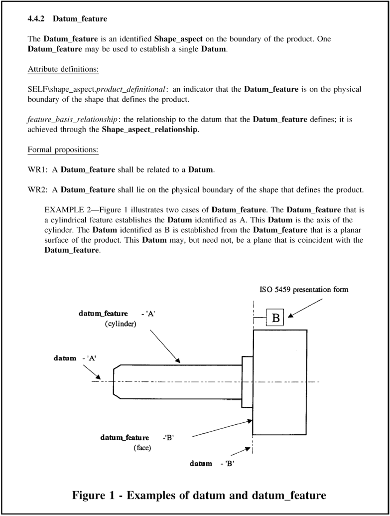
Datum: “A theoretically exact point, axis, or plane derived from the true geometric counterpart of a specified datum feature. A datum is the origin from which the location or geometric characteristics of features of a partare established ” [4].
Datum Feature: “ An actual feature of a part that is used to establish a datum ”[4].
Datum Feature Symbol: “ The symbolic means of indicating a datum feature consists of a capital letter enclosed in a square frame and a leader line extending from the frame to the concerned feature, terminating with a triangle ” [4].
Datum System: “ A group of two or more separate datums used as a combined reference for a toleranced feature ” [6].
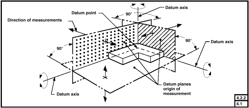
Datum Reference Frame: A framework that consists of three mutually perpendicular datum planes, three datum axes (located at the intersection of each pair of datum planes), and a datum point (that is located at the intersection of the three datum planes).
Datum Target: “ A specified point, line, or area on a part used to establish a datum ” [4].
Datum Target Frame: “ The datum targets are indicated by a circular frame divided in two compartments by a horizontal line. The lower compartment is reserved for a letter and a digit. The letter represents the datum feature and the digit the datum target number. The upper compartment is reserved for additional information, such as dimensions of the target area. If there is not sufficient space within the compartment, the information may be placed outside and connected to the appropriate compartment by a leader line ” [6].
Feature:“ The general term applied to a physical portion of a part, such as a surface, pin, tab, hole, or slot ” [4].
Feature Control Frame: “ The feature control frame
is a rectangular box containing the geometric
characteristic symbol and the form, orientation, profile,
runout, or location tolerance. If necessary, datum
references and modifiers applicable to the feature or the
datums are also contained in the box, e.g. ”
 [8].
[8].
Feature of Size:“ One cylindrical or spherical surface, or a set of two opposed elements or opposed parallel surfaces, associated with a size dimension ” [4].
Least Material Condition (LMC): “ The condition in which a feature of size contains the least amount of material within the stated limits of size — for example, maximum hole diameter, minimum shaft diameter ” [4].
Least Material Requirement: “ The least material requirement permits an increase in the stated geometrical tolerance when the concerned feature departs from its least material condition (LMC) ” [9].
Maximum Material Condition (MMC): “ The condition in which a feature of size contains the maximum amount of material within the stated limits of size — for example, minimum hole diameter, maximum shaft diameter ” [4].
Maximum Material Principle: “ The maximum material principle is a tolerancing principle which requires that the virtual condition for the toleranced feature(s) and, if indicated, the maximum material condition of perfect form for datum feature(s), shall not be violated ” [10].
Regardless of Feature Size (RFS):“The term used to indicate that a geometric tolerance or datum reference applies at any increment of size of the feature within its size tolerance”[4].
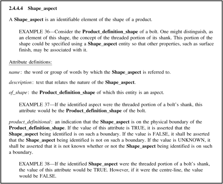
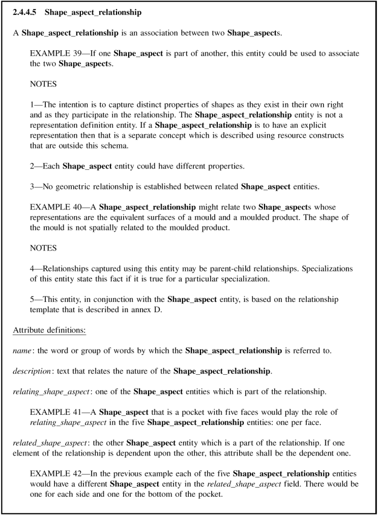
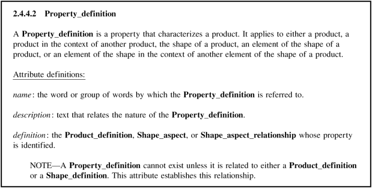
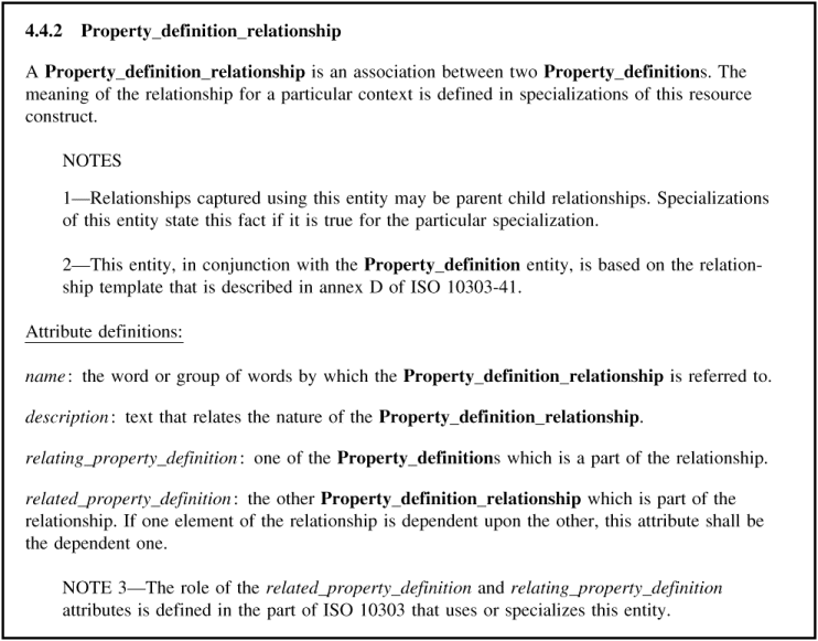
STEP integrated generic resources are a series of STEP parts that define resource constructs that are context-independent. The underlying structure of the DSCDM is based on four entities from the STEP integrated generic resources. These entities are Shape_aspect , Shape_aspect_relationship , Property_definition , and Property_definition_relationship . A review of these entities is presented in Appendix B of this paper.
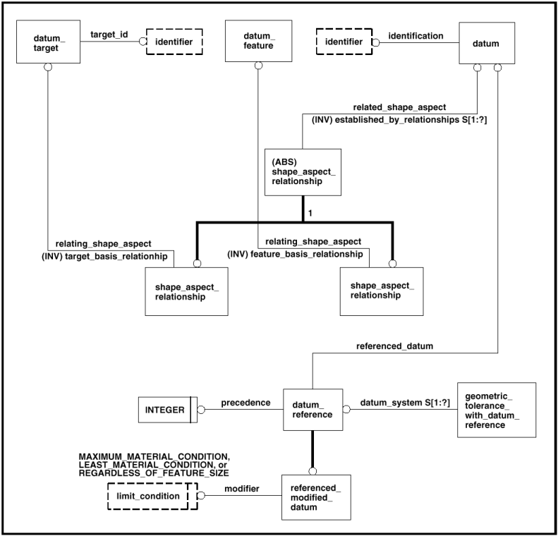
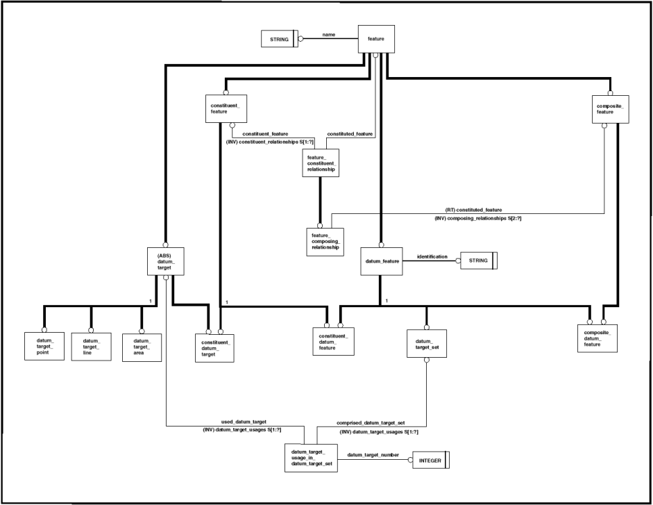
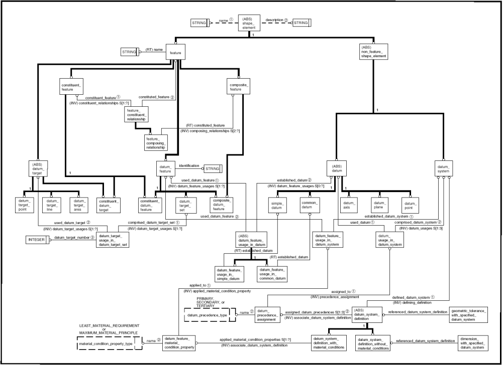
The DSCDM is presented in the EXPRESS-Gdiagram shown in Fig. 1. The entities are organized on the page such that the entities based on the Shape_aspect entity of STEP Part 41 [11] are at the top of the page. Immediately below the Shape_aspect based entities are the entities based on the Shape_aspect_relationship entity of STEP Part 41. At the bottom of the page are the entities based on the Property_definition entity of STEP Part 41. Note that the DSCDM does not actually contain entities based on the Property_definition_relationship entity of STEP Part 45 [12]. Instead, in the interest of simplicity, Property_definition based entities are related with attributes that have been included in the Property_definition based entities. For example,instead of specifying a Property_definition_relationship based entity in theDSCDM to relate the Datum_system_definition entity with the Datum_precedence_assignment entity, the relationship between these two entities is established by the assigned_datum_precedences attribute of the Datum_system_definition entity.
The definitions of the entities presented in Fig. 1 are defined below. These definitions are presented in theorder they appear on the page. That is, the Shape_aspect based entities are first, followed by the Shape_aspect_relationship based entities, and finally, the Property_definition based entities.
A Datum_system corresponds to a datum system (see Sec. 3 of this paper) that is comprised of one to three datums.
NOTE — The definition of datum system as defined in ISO 5459-1981 is given in Sec. 3 of this paper. However, for the purpose of this model, the definition of datum system has been extended so that a datum system may be comprised of a single datum.
Inverse attribute definitions:
datum_usages: The datum_usages attribute specifies a set of one to three Datum_usage_in_datum_system s. Each of the Datum_usage_in_datum_system s in this set corresponds to the usage of a datum in the datum system.
defining_definition: The defining_definition attribute specifies the Datum_system_definition that specifies the characteristics of the corresponding datum system (e.g., the order in which each datum is established within the datum system).
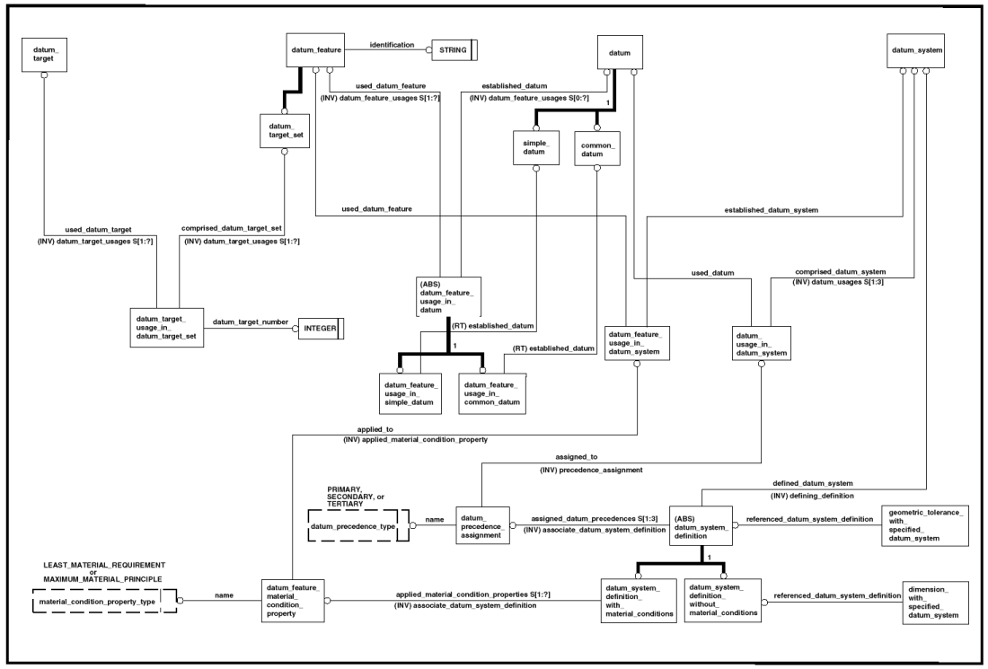
EXAMPLE — Both Figs. 2 (b) and (c) contain a feature control frame, each of which specifies a datum system that consists of three datums (datums A, B, and C). However, these two datum systems are different, as the order that the datums are established within each datum system differs (i.e., they have a different datum precedence). Figure 2 illustrates the effect that datum precedence has on a datum system.
Constraints:
WR1: Of the Datum_feature s specified as the used_datum_feature by the Datum_feature_usage_in_datum s that are specified as the datum_feature_usages by the Datum s that are specified as the used_datum by the Datum_usage_in_datum_system s that are specified as the datum_usages of the Datum_system , no Datum_feature may be specified more than once.
WR2: Of the Datum_target s specified as the used_datum_target by the Datum_target_usage_in_datum_target_set s specified as the datum_target_usage by the Datum_target_set s specified as the used_datum_feature by the Datum_feature_usage_in_datum s that arespecified as the datum_feature_usages by the Datums that are specified as the used_datum by the Datum_usage_in_datum_system s that are specified as the datum_usages of the Datum_system , no Datum_target may be specified more than once.
A Datum corresponds to a datum (see Sec. 3 of this paper). A Datum may be either a Simple_datum or a Common_datum .
Inverse attribute definitions:
datum_feature_usages: The datum_feature_usages attribute specifies a set of zero or more Datum_feature_usage_in_datum s. Each of the Datum_feature_usage_in_datum s in this set corresponds to the usage of a datum feature in establishing the datum.
A Simple_datum is a type of Datum that corresponds to a datum that is established from exactly one datum feature.
Constraints:
WR1: Each Simple_datum shall be specified as the used_datum by at least one Datum_usage_in_datum_system .
WR2: Each Simple_datum shall specify exactly one Datum_feature_usage_in_simple_datum as its datum_feature_usages .
A Common_datum is a type of Datum that corresponds to a datum that is established from more than one datum feature.
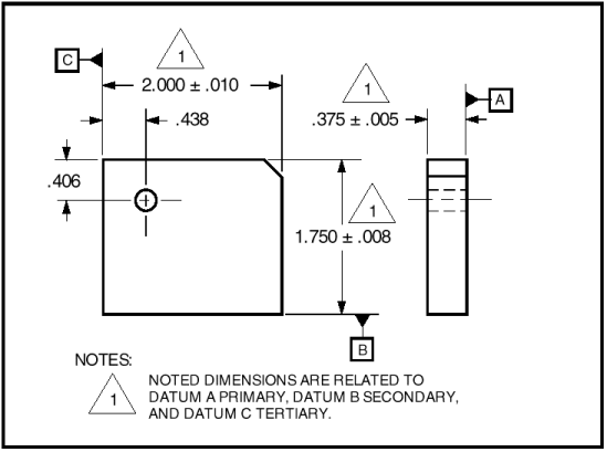
EXAMPLE — The technical drawing presented in Fig. 3 shows a datum plane that is established from two datum features (datum features A and B).
Constraints:
WR1: Each Common_datum shall be specified as the used_datum by at least one Datum_usage_in_datum_system .
WR2: Each Common_datum shall specify more than one Datum_feature_usage_in_common_datum as its datum_ feature_usages.
A Datum_feature corresponds to a datum feature (see Sec. 3 of this paper). A Datum_feature may be a Datum_target_set .
NOTE — On technical drawings, a feature is
typically identified as a datum feature by means of a
datum feature symbol, e.g.,  .
.
NOTE — The concept of datum feature in the DSCDM applies to features that are used to establish one or more datums. Features that may be used as datum features include“partial ”features and datum target sets, as well as“complete” and composite features. The concept of datum feature in the DSCDM does not pertain to features in which only a portion of the feature (i.e., a“partial” feature or a datum target set) is used to establish one or more datums. “Partial” and composite features are discussed in Sec. 10.2 of this paper.
Attribute definitions :
identification: Theidentification attribute specifies the string value by which the corresponding datum feature is referred.
).
EXAMPLE — Two datum features are identified in Fig. 3, datum feature A and datum feature B.
Inverse attribute definitions:
datum_ feature_usages: The datum_feature_usages attribute specifies a set of one or more Datum_feature_usage_in_datum s.Each of the Datum_feature_usage_in_datum s in this set corresponds to the usage of the datum feature in establishing a datum.
Constraints:
WR1: There shall be at most one Datum_feature_usage_in_simple_datum in the set of Datum_feature_usage_in_datum s specified as the datum_ feature_usages .
A Datum_target_set is a type of Datum_feature that corresponds to a set of one or more datum targets (see Sec. 3 of this paper).
 ) indicate in which datum target sets the
associated datum targets are used.
) indicate in which datum target sets the
associated datum targets are used.
Inverse attribute definitions:
datum_target_usages: Thedatum_target_usages attribute specifies a set of one or more Datum_target_usage_in_datum_target_set s. Each of the Datum_target_usage_in_datum_target_set s in this set corresponds to the usage of a datum target in the datum target set.
ADatum_targetcorresponds to a datum target (see Sec. 3 of this paper).
NOTE — Datum targets are typically used in situations where it is inappropriate to specify an entire surface as a datum feature.
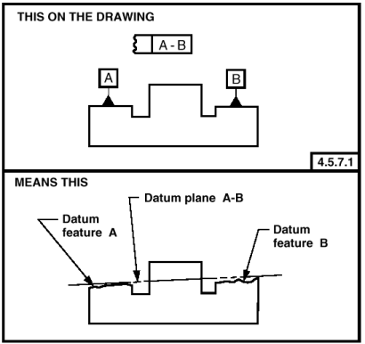
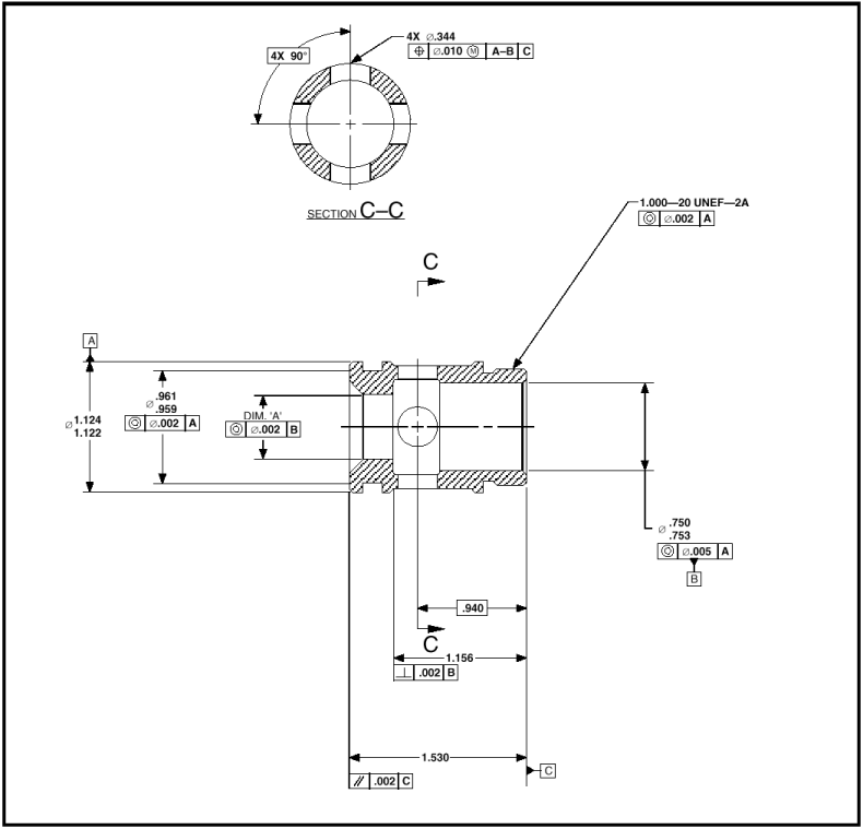
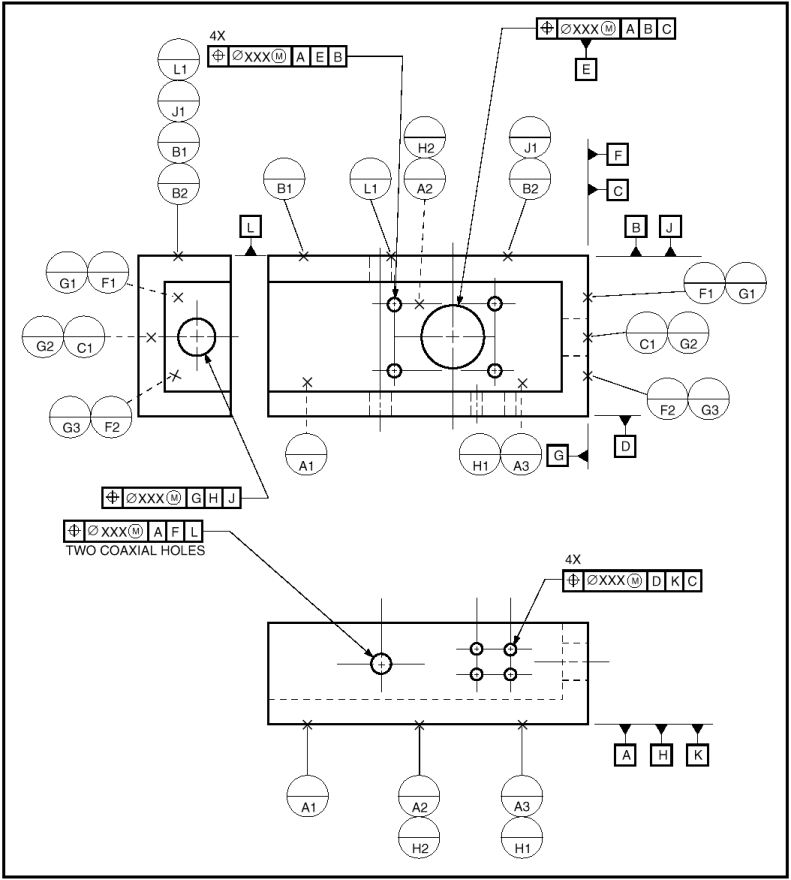
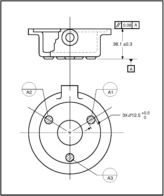
EXAMPLE — There are six datum targets shown in Fig. 4. Four of these datum targets are datum target points, each of which is represented by an ×. The other two datum targets are datum target areas, each of which is represented by a cross-hatched circular area.
Inverse attribute definitions:
datum_target_usage s: The datum_target_usage sattribute specifies a set of one or more Datum_target_usage_in_datum_target_set s. Each of the Datum_target_usage_in_datum_target_set s in this set corresponds to the usage of the datum target in a datum target set.
A Datum_usage_in_datum_system corresponds to the usage of a datum in a datum system.
Attribute definitions:
comprised_datum_system : The comprised_datum_system attribute specifies the Datum_system that corresponds to the datum system that is either partially or wholly comprised of the corresponding datum.
used_datum: The used_datum attribute specifies the Datum that corresponds to the datum that is used in the corresponding datum system.
Inverse attribute definitions:
precedence_assignment : The precedence_assignment attribute specifies the Datum_precedence_assignment that corresponds to the specification of the order in which the datum is established within the datum system.
Constraints:
UR1: The combination of comprised_datum_system and used_datum shall be unique within a population of Datum_usage_in_datum_system .
WR1: The Datum specified as the used_datum shall either be a Common_datum or Simple_datum .
A Datum_feature_usage_in_datum_system corresponds to the usage of a datum feature in establishing a datum system.
NOTE — The relationship between a Datum_feature and a Datum_system is indirectly established with a Datum_feature_usage_in_datum , a Datum , and a Datum_usage_in_datum_system . Therefore, a Datum_feature_usage_in_datum_system should not be used unless it is necessary to indicate the application of either the least material requirement or the maximum material principle (see Sec. 3 of this paper) to a datum feature within the context of a datum system. In essence, a Datum_feature_usage_in_datum_system corresponds to a datum feature in the context of a datum system.
Attribute definitions:
established_datum_system : The established_datum_system attribute specifies the Datum_system that corresponds to the datum system that is established from the corresponding datum feature.
used_datum_feature : The used_datum_feature attribute specifies the Datum_feature that corresponds to the datum feature that is used to establish the corresponding datum system.
Inverse attribute definitions:
applied_material_condition_property : The applied_material_condition_property attribute specifies the Datum_feature_material_condition_property that corresponds to the specification of a material condition property (i.e., least material requirement or the maximum material principle ) that is applied to the datum feature in the context of the datum system.
Constraints:
WR1: The Datum_feature specified as the used_datum_ feature shall be specified as the used_datum_ feature by a Datum_feature_usage_in_datum that specifies a Datum as the established_datum , and that Datum shall be specified as the used_datum by a Datum_usage_in_datum_system that specifies the same Datum_system as the comprised_datum_system , as is specified as the established_datum_system by the Datum_feature_usage_in_datum_system .
A Datum_feature_usage_in_datum corresponds to the usage of a datum feature in establishing a datum. A Datum_feature_usage_in_datum is either a Datum_feature_usage_in_simple_datum or a Datum_feature_usage_in_common_datum .
Attribute definitions:
established_datum: The established_datum attribute specifies the Datum that corresponds to the datum that is established from the corresponding datum feature.
used_datum_feature : The used_datum_feature attribute specifies the Datum_feature that corresponds to the datum feature that is used to establish the corresponding datum.
A Datum_feature_usage_in_simple_datum is a type of Datum_feature_usage_in_datum that corresponds to the usage of a datum feature in establishing a datum that is established from exactly one datum feature.
Attribute definitions:
established_datum: The established_datum attribute specifies the Simple_datum that corresponds to the datum that is established from the corresponding datum feature.
A Datum_feature_usage_in_common_datum is a type of Datum_feature_usage_in_datum that corresponds to the usage of a datum feature in establishing a datum that is established from more than one datum feature.
Attribute definitions:
established_datum : The established_datum attribute specifies the Common_datum that corresponds to the datum that is established, in part, from the corresponding datum feature.
A Datum_target_usage_in_datum_target_set corresponds to the usage of a datum target in a set of datum targets.
NOTE — On technical drawings, the usage of a
datum target in a datum target set is indicated with
a datum target frame, e.g., the symbolin
Fig. 4. The letter in the lower compartment of a
datum target frame identifies the datum target set in
which the associated datum target is used, and the
number (datum target number) in the lower compartment
is an integer value by which the associated datum
target is identified within the datum target set.
EXAMPLE — The datum target
frame in Fig. 4 indicates that the datum target
pointed to by the connected leader line is used
within datum target set A.
Attribute definitions:
comprised_datum_target_set : The comprised_datum_target_set attribute specifies the Datum_target_set that corresponds to the datum target set that is either partially or wholly comprised of the corresponding datum target.
datum_target_number : The datum_target_number attribute specifies the integer value by which the corresponding datum target is identified within the corresponding datum target set.
EXAMPLE — The datum target number
“1”in the datum target
frame of Fig. 4 is the integer value by which the
associated datum target is identified within datum
target set A.
used_datum_target : The used_datum_target attribute specifies the Datum_target that corresponds to a datum target that is used in the corresponding datum target set.
Constraints:
UR1: The combination of used_datum_target and defined_datum_target_set shall be unique within a populationof Datum_target_usage_in_datum_target_set .
UR2: The combination of datum_target_number and defined_datum_target_set shall be unique within a population of Datum_target_usage_in_datum_target_set .
A Datum_system_definition corresponds to the specification of the characteristics of a datum system. These characteristics include the order in which the datums are established within the datum system and anymaterial condition properties (i.e., least material requirement or maximum material principle ) that are explicitly applied to datum features within the context of the datum system. A Datum_system_definition shall either be a Datum_system_definition_with_material_conditions or a Datum_system_definition_without_material_conditions .
NOTE — On technical drawings, the characteristics of a datum system are typically specified in a feature control frame.
Attribute definitions:
defined_datum_system : The defined_datum_system attribute specifies the Datum_system that corresponds to the datum system the characteristics of which are specified.
assigned_datum_ precedences : The assigned_datum_ precedences attribute specifies a set of one to three Datum_ precedence_assignment s. Each of the Datum_ precedence_assignment s in this set corresponds to the specification of the order in which a datum is established within the datum system.
Constraints:
WR1: Each Datum_ precedence_assignment within the set of Datum_ precedence_assignment s specified as the assigned_datum_ precedences shall specify as its assigned_to a Datum_usage_in_datum_system that specifies as its comprised_datum_system the same Datum_system as specified as the defined_datum_system .
WR2: A Datum_ precedence_assignment that has a name of TERTIARY shall not exist within the set of Datum_ precedence_assignment s specified as the assigned_datum_ precedences unless a Datum_ precedence_assignment exists within that set that has a name of SECONDARY.
WR3: A Datum_ precedence_assignment that has a name of SECONDARY shall not exist within the set of Datum_ precedence_assignment s specified as the assigned_datum_ precedences unless a Datum_ precedence_assignment exists within that set that has aname of PRIMARY.
WR4: Each Datum_system_definition shall be specified as the referenced_datum_system_definition by at least one Geometric_tolerance_with_specified_datum_system or Dimension_with_specified_datum_system .
A Datum_system_definition_with_material_conditions is a type of Datum_system_definition that corresponds to a specification of a datum system that specifies the application of material condition properties (i.e., least material requirement or maximum material principle ) to one or more datum features within the context of the datum system.
 ) that is
preceded immediately by a datum feature letter or at
least one maximum material principle symbol(
) that is
preceded immediately by a datum feature letter or at
least one maximum material principle symbol(
 ) that is preceded immediately by a datum
feature letter, e.g.,
) that is preceded immediately by a datum
feature letter, e.g., 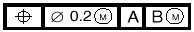 (the
symbol after the tolerance value is associated with the
toleranced feature and its representation is not within
the scope of this paper).
(the
symbol after the tolerance value is associated with the
toleranced feature and its representation is not within
the scope of this paper).
Attribute definitions:
applied_material_condition_properties : The applied_material_condition_properties attribute specifies a set of one or more Datum_feature_material_condition_property s. Each of the Datum_feature_material_condition_property s in this set corresponds to the specification of a material condition property that is explicitly applied to a datum feature within the context of the datum system.
Constraints:
WR1: Each Datum_feature_material_condition_property within the set of Datum_feature_material_condition_property s specified as the applied_material_condition_properties shall specify as its applied_to a Datum_feature_usage_in_datum_system that specifies as its established_datum_system the same Datum_system as specified as the defined_datum_system .
NOTE — The defined_datum_system attribute referred to in WR1 is inherited from the Datum_system_definition entity of which this entity is a subtype.
A Datum_system_definition_without_material_conditions is a type of Datum_system_definition that corresponds to a specification of a datum system in which no material condition properties (i.e., least materialrequirement or maximum material principle ) are specified.
) that is immediately preceded by a
datum feature letter nor a maximum material
principle symbol ( ) that is
immediately preceded by a datum feature letter, e.g.,
 .
.
NOTE — On technical drawings, a datum system specification that corresponds to a Datum_system_definition_without_material_conditions could also be specified in a dimension related note; see Fig. 5.
A Datum_precedence_assignment corresponds to the specification of the order in which a datum is established within a datum system.
NOTE — The Datum_precedence_assignment entity is based on the Property_definition entity of STEP Part 41 [11].
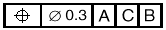
EXAMPLE — Figure2 (b) contains a feature control frame that specifies a datum system in which datum A is the primary datum, datum B is the secondary datum, and datum C is the tertiary datum. Similarly, Fig. 2 (c) contains a feature control frame that specifies a datum system in which datum A is the primary datum, datum C is the secondary datum, and datum B is the tertiary datum.
Attribute definitions:
assigned_to: The assigned_to attribute specifies a Datum_usage_in_datum_system . In essence, the Datum_usage_in_datum_system corresponds to the datum within the context of the datum system to which the datum precedence is assigned.
EXAMPLE — In Fig. 6, datum feature C (the end surface of the part that is shown on the right side) isused to establish a datum plane. The top-most feature control frame asserts that this datum is the secondary datum within the context of one datum system. Furthermore, the bottom-most feature control frame asserts that this datum is the primary datum within the context of another datum system.
name: The name attribute specifies the value of the assigned datum precedence. Valid values for the name are PRIMARY, SECONDARY, and TERTIARY.
Inverse attribute definitions:
associate_datum_system_definition: The associate_datum_system_definition attribute specifies the Datum_system_definition that corresponds to the datum system specification to which the datum precedence is associated.
Constraints:
UR1: The combination of name and associate_datum_system_definition shall be unique within a population of Datum_precedence_assignment s.
A Datum_feature_material_condition_property corresponds to the specification of a material condition property (i.e., least material requirement or maximum material principle ) that is explicitly applied to a datum feature within the context of a datum system.
Attribute definitions:
applied_to: The applied_to attribute specifies a Datum_feature_usage_in_datum_system . In essence, the Datum_feature_usage_in_datum_system corresponds to the datum feature within the context of the datum system to which the material condition property is applied.
name : The name attribute specifies the value by which the material condition property is known. Valid valuesfor the name are LEAST_MATERIAL_REQUIREMENT and MAXIMUM_MATERIAL_PRINCIPLE (see Sec. 3 of this paper).
symbol in a feature control frame of a
technical drawing, e.g., 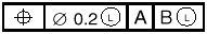 (the
symbol after the tolerance value is associated with the
toleranced feature and its representation is not within
the scope of this paper).
(the
symbol after the tolerance value is associated with the
toleranced feature and its representation is not within
the scope of this paper).
NOTE — A
Datum_feature_material_condition_property that
has a name of MAXIMUM_MATERIAL_PRINCIPLE
corresponds to a datum feature letter followed by the
symbol in a feature control frame of a
technical drawing, e.g., 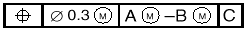 (the
symbol after the tolerance value is
associated with the toleranced feature and its
representation is not within the scope of this
paper).
(the
symbol after the tolerance value is
associated with the toleranced feature and its
representation is not within the scope of this
paper).
NOTE — It shall be understood that the regardless of feature size principle (see Sec. 3 of this paper) shall be in effect in cases where the datum feature is a feature of size (see Sec. 3 of this paper) and a Datum_feature_material_condition_property is not specified.
Inverse attribute definitions:
associate_datum_system_definition : The associate_datum_system_definition attribute specifies the Datum_system_definition_with_material_conditions that corresponds to the datum system specification to which the material condition property is associated.
The Geometric_tolerance_with_specified_datum_system entity is not completely defined here, as it is not within the scope of this paper. However, the referenced_datum_system_definition attribute of this entity is defined to illustrate how the DSCDM could be tied into a larger GD&T; data model.
Attribute definitions:
referenced_datum_system_definition : The referenced_datum_system_definition attribute specifies the Datum_system_definition that corresponds to the datum system specification that is referenced by the geometric tolerance.
The Dimension_with_specified_datum_system entity is not completely defined here, as it is not within the scope of this paper. However, the referenced_datum_system_definition attribute of this entity is defined to illustrate how the DSCDM could be tied into a larger GD&T; data model.
NOTE — While the data modeled with the Datum_system_definition entity is associated almost exclusively with geometric tolerances, clause 4.4 of ASME Y 14.5M [4] describes the usage of this data with linear and angular dimensions. The Dimension_with_specified_datum_system entity is shown in Fig. 1 to illustrate this usage.
EXAMPLE — The three linear dimensions presented in Fig. 5 reference NOTE 1. This note is a specification for a datum system that specifies that the primary datum is established from datum feature A, the secondary datum is established from datum feature B, and the tertiary datum is established from datum feature C.
Attribute definitions:
referenced_datum_system_definition : The referenced_datum_system_definition attribute specifies the Datum_system_definition_without_material_conditions that corresponds to the datum system specificationthat is referenced by the dimension.
A pseudo EXPRESS-G diagram of the datum system related portion of the Part 47 model is presented inFig. 7. The term“pseudo”is used because non-standard EXPRESS-G is employed to indicate the constraints placed on the Datum_target , Datum_feature , and Datum entities (e.g., the model shows three Shape_aspect_relationship entities). Additionally, the EXPRESS-G diagram does not show that the Datum_target , Datum_feature , and Datum entities are subtypes of the Shape_aspect entity of STEP Part 41[11].
The definitions of the entities shown in Fig. 7 are provided in Tables 1 – 6. These definitions are taken from STEP Part 47 [2].
NOTE — The clause and figure numbers specified within Tables 1 – 6 are from STEP Part 47 and should not be confused with the clause and figure numbers of this paper.
This section discusses the differences between the DSCDM and portions of the model presented in STEP Part 47 [2] that are related to datums. Inasmuch as STEP Part 47 is an integrated generic resource, it should notnecessarily be as specialized as the DSCDM. Still, it is useful to make certain comparisons between these two models to observe how they differ in representing the datum related concepts presented in some of the GD&T drawing-based; standards. It is particularly useful to note cases that cannot be clearly represented with the Part 47 model and in which the deficiency is not due to the generic nature of the Part 47 model.
EXAMPLE — A STEP application protocol that incorporates the Datum_feature entity from STEP Part 47 will not be able to support multiple use datum features (see Sec. 6.3).
One of the main differences between the Part 47 model and the DSCDM is that the Part 47 model has no entities that are equivalent to the Datum_system and Datum_system_definition entities of the DSCDM. Two independent comments were submitted against the STEP Part 47 DIS [15] document indicating that the concept of datum precedence only made sense within the context of a datum system. Additionally, one of those comments also indicated that the modifier for the Datum_reference only made sense in the context of a datum system. Concurring with those comments, the Datum_system and Datum_system_definition entities were incorporated within the DSCDM.
In the DSCDM the identification attribute is on the Datum_feature entity; in contrast, in the Part 47 model the identification attribute is on the Datum entity. In practice, it is the datum feature to which an identifier is assigned. ASME Y14.5M [4] states,“Each datum feature of a part requiring identification shall be assigned a different letter.” Furthermore, datums associated with datum systems are identified by the datum features from which they are established. In cases in which a datum is established from a single datum feature, the location of the identification attribute may seem moot, because if the identification attribute is placed on the Datum entity, the name of the associated datum feature could easily be derived. However, in cases in which a datum is established from more than one datum feature, the Part 47 model produces ambiguous results because it is impossible to determine the name of the datum features from the value of the identification attribute on a Datum .The DSCDM does not have this ambiguity, as the identification attribute is on the Datum_feature entity.
 feature control
frame of the position tolerance in Fig. 6 indicates
that the primary datum is established from datum
feature A in conjunction with datum feature B. If the
Part 47 model was used to describe this requirement,
the identification attribute of the Datum
entity would have a value of“A – B.”
However, it would be unclear as to which datum feature
is identified as A and which datum feature is
identified as B.
feature control
frame of the position tolerance in Fig. 6 indicates
that the primary datum is established from datum
feature A in conjunction with datum feature B. If the
Part 47 model was used to describe this requirement,
the identification attribute of the Datum
entity would have a value of“A – B.”
However, it would be unclear as to which datum feature
is identified as A and which datum feature is
identified as B.
NOTE — As the Datum and Datum_feature entities in the Part 47 model are subtypes of the Shape_aspect entity of STEP Part 41 [11], they both inherit a name attribute. However, as a Datum_feature corresponds to an actual feature of a part it is likely that the name attribute will not be available for the datum feature identifying letter because it will likely be used for another purpose (e.g., the name given to a feature prior to its promotion to a datum feature). Furthermore, as datums are identified solely for GD&T; purposes it is likely that the inherited name attribute on the Datum entity would be available, thereby making the identification attribute on the Datum entity not only misplaced but redundant.
The Part 47 model fails to account for the fact that a datum feature may be used to establish multiple datums, whereas the DSCDM does account for this fact. In the Part 47 model, the feature_basis_relationship attribute and WR1 on the Datum_feature entity specify that a Datum_feature shall be related to exactly one Datum . On the other hand, in the DSCDM the inverse datum_feature_usages attribute on the Datum_feature entity constrains the number of Datum s that shall be established from a Datum_feature to one or more.
 ). Also, Fig. 6
shows that datum feature B (the inner hole surface on
the right side) is used to establish the primary datum
(another center axis) of the datum system specified by
a concentricity tolerance and a perpendicularity
tolerance (i.e.,
). Also, Fig. 6
shows that datum feature B (the inner hole surface on
the right side) is used to establish the primary datum
(another center axis) of the datum system specified by
a concentricity tolerance and a perpendicularity
tolerance (i.e.,  , and
, and  ).
Furthermore, both datum features Aand B are used once
again to establish the primary datum (yet another
center axis) of the datum system specified by the
position tolerance (i.e.,
).
Furthermore, both datum features Aand B are used once
again to establish the primary datum (yet another
center axis) of the datum system specified by the
position tolerance (i.e.,  ). As the Part 47
model limits the number of datums that may be
established from a datum feature to one, this situation
cannot be represented with the Part 47 model.
). As the Part 47
model limits the number of datums that may be
established from a datum feature to one, this situation
cannot be represented with the Part 47 model.
The Part 47 model fails to account for the fact that a datum target may be used to establish multiple datums, whereas the DSCDM does account for this fact. In the Part 47 model the target_basis_relationship attribute and WR1 on the Datum_target entity specify that a Datum_target shall be related to exactly one Datum . On the other hand, the DSCDM does not specify a direct relationship between a Datum_target and a Datum . Instead,in the DSCDM the relationship between a Datum_target and a Datum is specified indirectly via the Datum_target_set entity and the two relationship entities Datum_target_usage_in_datum_target_set and Datum_feature_usage_in_datum . In the DSCDM the constraints on Datum_target and Datum_feature correspond to the assertion that a datum target shall be used in at least one datum target set and because a datum target set is a type of datum feature, the datum target set shall be used to establish at least one datum. The technical drawing presented in Fig. 8 shows nine datum targets (datum target points are indicated by the × symbols), six of which are used to establish multiple datums.
 and
and  datum target frames is associated with two datum target
sets, F and G, each of which is used to establish a
separate datum. As the Part 47 model limits the number
of datums that may be established from a datum target
to one, this situation cannot be represented with the
Part 47 model.
datum target frames is associated with two datum target
sets, F and G, each of which is used to establish a
separate datum. As the Part 47 model limits the number
of datums that may be established from a datum target
to one, this situation cannot be represented with the
Part 47 model.
In the DSCDM, a Datum_target_set is a type of Datum_feature . The Part 47 model has no entity that is equivalent to the Datum_target_set entity. Furthermore, the Part 47 model prevents the Datum_feature entity or a specialization (i.e., subtype) of it to serve as a set of datum targets. That is, in the Part 47 model the attributes target_basis_relationship andfeature_basis_relationship on the Datum_target and Datum_feature entities, respectively, in association with WR1 on each of these entities, prevent a Datum_target from beingrelated to a Datum_feature via a Shape_aspect_relationship .
EXAMPLE — In the technical drawing presented in
Fig. 4, the three datum target points (×
symbols are used to indicate datum target points)
that are connected to the ,  and
and  datum target frames make updatum
target set A. Additionally, the two datum target
areas (hatched regions are used to indicate datum
target areas) that are connected to the
datum target frames make updatum
target set A. Additionally, the two datum target
areas (hatched regions are used to indicate datum
target areas) that are connected to the  and
and  datum target frames constitute datum
target set B. Also, the datum target point that is
connected to the
datum target frames constitute datum
target set B. Also, the datum target point that is
connected to the  datum target
frame makes up datum target set C.
datum target
frame makes up datum target set C.
The Part 47 model fails to account for the fact that multiple datum target numbers may be associated with a datum target, whereas the DSCDM does account for this fact. In the Part 47 model, the definition for the target_id attribute on the Datum_target entity indicates that the use of this attribute is to associate adatum target number with a datum target. However, the placement of this attribute on the Datum_target entity only allows a single datum target number to be associated with a datum target, which is not surprising as the Part 47 model only allows a datum target to be associated with a single datum. On the other hand, in the DSCDM the placement of the datum_target_number attribute on the Datum_target_usage_in_datum_target_set entity permits a different datum target number to be assigned to each usage of a datum target in a datum target set.
The technical drawing presented in Fig. 8 shows several instances in which a datum target is identified by multiple datum target numbers, one for each usage of a datum target in a datum target set.
EXAMPLE — The datum target point in Fig. 8 that
is connected to the and  datum target frames isassociated with two datum
targets sets, C and G. This datum target is
identified by a datum target number of
“1” when it is associated with datum
target set C and is identified by a datum target
number of“2”when it is associated with
datum target set G.
datum target frames isassociated with two datum
targets sets, C and G. This datum target is
identified by a datum target number of
“1” when it is associated with datum
target set C and is identified by a datum target
number of“2”when it is associated with
datum target set G.
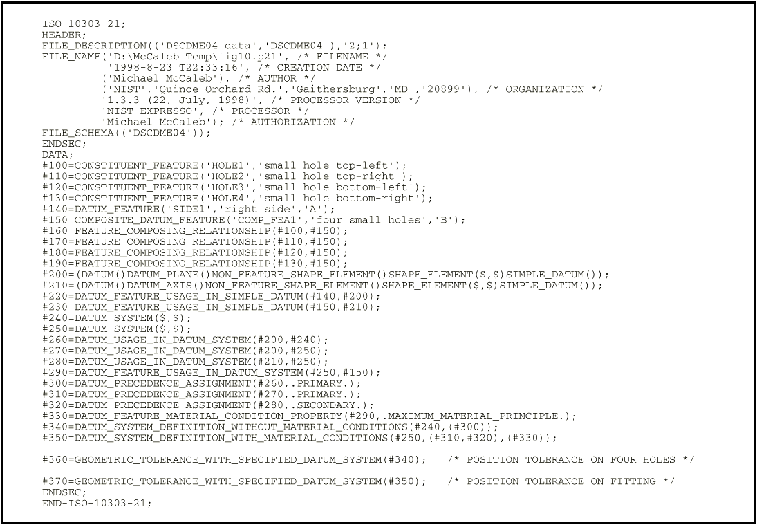
A composite datum feature is a datum feature that is composed of other features. Figures 9 and 10 depict two examples of composite datum features.
Neither the Part 47 model nor the DSCDM have an explicit entity that corresponds to a composite datum feature. However, it is of interest to examine how composite datum features may be represented using these two models.
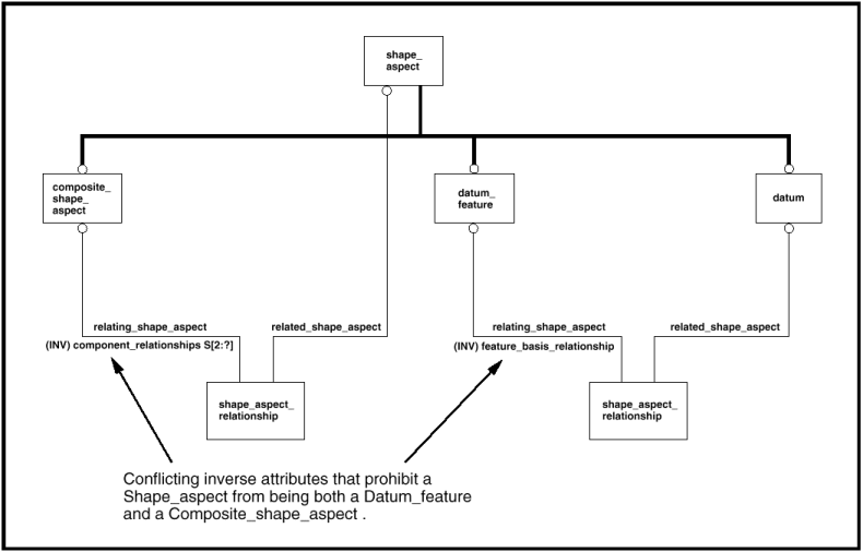
The model presented in STEP Part 47 has a Composite_shape_aspect entity, the intent of which is to group Shape_aspects for a purpose. At first glance this seems like a perfect match — a Shape_aspect that is a Datum_feature as well as a Composite_shape_aspect could represent a composite datum feature. This usage of Composite_shape_aspect is even mentioned in a note in clause 4.4.1 of STEP Part 47 [2] (see Table 1 of this paper). Unfortunately, the feature_basis_relationship inverse attribute on the Datum_feature entity requires that a Datum_feature be specified as the relating_shape_aspect by exactly one Shape_aspect_relationship . Conversely, the component_relationships inverse attribute on the Composite_shape_aspect entity requires that a Composite_shape_aspect be specified as the relating_shape_aspect by two or more Shape_aspect_relationships (these Shape_aspect_relationships relate the Composite_shape_aspect with the Shape_aspects from which it is composed). This conflict between the two inverse attributes prohibits a Shape_aspect from being both a Datum_feature and a Composite_shape_aspect . Figure 11 is a pseudoEXPRESS-G diagram illustrating this conflict.
Though the DSCDM does not explicitly address the composite datum feature, the DSCDM is constructed suchthat composite datum features may be addressed by incorporating the DSCDM into a more complete GD&T model; that has an entity similar to the Composite_shape_aspect entity or by further specializing the Datum_feature entity .
In summary, the DSCDM is designed such that it may be extended to address composite datum features, whereas the Part 47 model is constructed such that even the entities that it indicates should be used to address composite datum features cannot be used for this purpose.
The Part 47 model and the DSCDM differ in two ways with respect to the assignment of datum precedence.
The first difference is that datum precedence is more rigorously defined in the DSCDM than in the Part 47 model. For example, the only constraint associated with the precedence attribute in the Part 47 model is that it must be an integer value that is greater than zero. However, the DSCDM has several constraints that ensure that the datums of the datum system have a valid precedence value assigned to them. For example, the UR1 constraint on the Datum_precedence_assignment entity corresponds to the assertion that no two datums of a datum system shall have the same precedence value. This lack of rigor in the Part 47 model may be attributed to the fact that STEP Part 47 [2] is a generic integrated resource and as such is not necessarily intended to fully define the requirements.
The second difference is that in the Part 47 model the precedence attribute on the Datum_reference entity isused to assign a precedence directly to a Datum , as opposed to in the DSCDM where the assigned_to attribute on the Datum_precedence_assignment entity is used to assign a precedence to a Datum_usage_in_datum_system . Inasmuch as the Datum_usage_in_datum_system entity corresponds toa datum in the context of a datum system, the DSCDM structure asserts that the precedence is assigned to a datum in the context of a datum system.
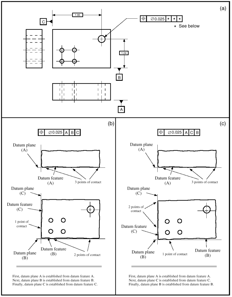
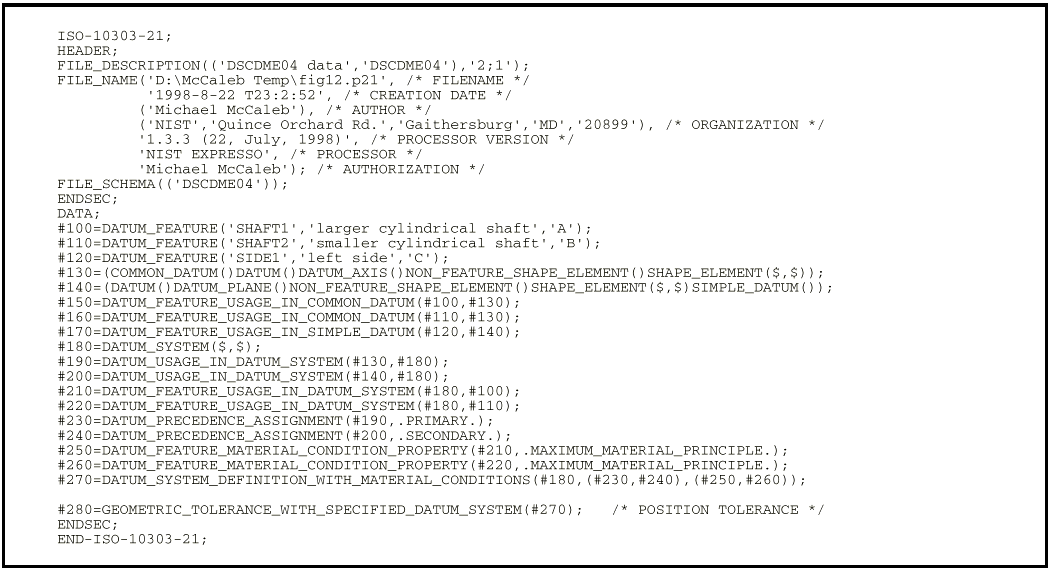
The Part 47 model is inconsistent with ASME Y14.5M [4] with regard to modifiers, whereas the DSCDM is consistent with ASME Y14.5M in this regard. Clause 4.5.7 of ASME Y14.5M states,“Where more than one datum feature is used to establish a single datum, the appropriate datum reference letters and associated modifiers, separated by a dash, are entered in one compartment of a feature control frame.”This statement indicates that modifiers are associated with datum features (see Fig. 12). However, in the Part 47 model the Referenced_modified_datum entity is used to associate modifiers with datums, not datum features. On the other hand, in the DSCDM the Datum_feature_material_condition_property entity is used to associate modifiers with datum features. (This association is made indirectly through the Datum_feature_usage_in_datum_system entity, as the DSCDM asserts that a modifier is applied to a datum feature in the context of a datum system.)
EXAMPLE — In Fig. 12, the symbol
following the letter“A”in the feature
control frame associates the maximum material
principle with datum feature A. Likewise, the
symbol following the
letter“B” in the feature control frame
associates the maximum material principle with
datum feature B.
One may argue that if modifiers are directly associated with datums, as in the Part 47 model, they are indirectly associated with the datum features that establish those datums. However, this contrivance fails in cases in which the requirements are such that all the datum features from which a common datum is established are not to beassociated with the same modifier.
In the DSCDM the Dimension_with_specified_datum_system corresponds to a type of dimension thatreferences a datum system specification. The Part 47 model has no entity that is equivalent to the Dimension_with_specified_datum_system entity.
NOTE — Clause 4.4 of ASME Y14.5M [4] describes dimensions that reference datum system specifications.
EXAMPLE — The technical drawing presented in Fig. 5 shows three linear dimensions that reference a datum system specification.
The Part 47 model cannot be used to represent datums that are not directly established from datum features or datum targets. This is because the attributes and rules on the Datum , Datum_feature , and Datum_target entities assert that each datum shall be established from one or more datum features or datum targets, that each datum feature shall be used to establish a single datum, and that each datum target shall be used to establish a single datum. In contrast, the DSCDM only requires that the relationship between the datum feature(s) from which a datum is established be specified for those datums that are used to establish a datum system. That is, for adatum not used to establish a datum system (some datums may just be the origin of one or more dimensions), the DSCDM does not require the corresponding Datum to be related to a Datum_feature via the Datum_feature_usage_in_datum entity.
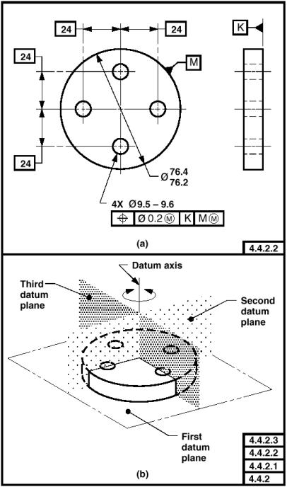
NOTE — Although the datum planes that are labeled “Second datum plane”and“Third datum plane” in Fig. 13 are not part of a datum system, they are part of a datum reference frame. Datum reference frames are not modeled in the DSCDM (datum reference frames are discussed in Appendix D of this paper). However, because the DSCDM does not require a datum to be part of a datum system and does notrequire a datum to be established from a datum feature, the DSCDM may be incorporated into a larger model that does include datum reference frames.
This paper has presented a data model (the DSCDM) that covers the concepts of datum systems, datums, datum features, and datum targets. Furthermore, for comparison purposes, this paper has presented the datum relatedportions of the data model given in STEP Part 47 [2]. In presenting the DSCDM, this paper has used numerous diagrams and examples from existing GD&T; drawing-based standards and associated reference books. These diagrams and examples not only provided assistance in explaining the DSCDM but also provided a set of test cases by which the quality of the DSCDM and the Part 47 model were evaluated. This evaluation demonstrated the robustness of the DSCDM and the brittleness of the Part 47 model. Accordingly, it is hoped that the DSCDM may serve as a starting point for the development of more comprehensive GD&T; data models, thereby enabling the electronic exchange of GD&T; data among the design, manufacturing, and inspection divisions of an enterprise.
As the data models in this paper are presented in EXPRESS-G notation, this overview is provided to aid those who may be unfamiliar with EXPRESS-G.
Data models formally define data objects and relationships among data objects for a domain of interest. Some typical applications of data models include supporting the development of databases and enabling the exchange of data for a particular area of interest.
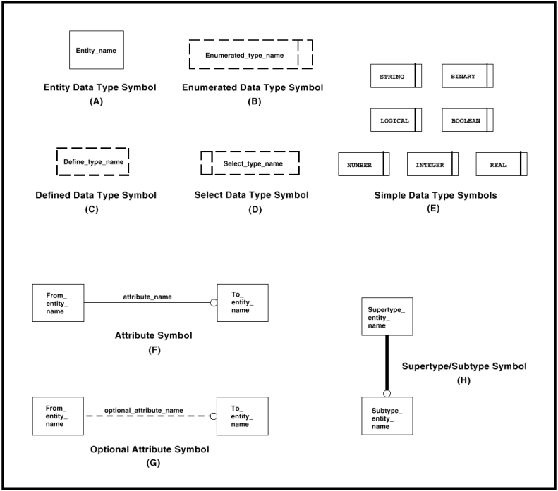
Data models are specified in a data modelling language. EXPRESS is a data modelling language defined inISO 10303-11, the EXPRESS Language Reference Manual [3]. EXPRESS-G is a graphical notation that supports a subset of the EXPRESS language. One of the advantages of using EXPRESS-G over EXPRESS is that the structure of a data model can be presented in a more understandable manner. A disadvantage of EXPRESS-G is that complex constraints cannot be formally specified. Figure A.2 depicts the symbols used in the EXPRESS-G notation. The meanings of these symbols are listed below.
Entity Data Type Symbol: An entity data type symbol [see Fig. A.2 (A)] represents a real or conceptual object of interest.
Attribute Symbol: An attribute symbol [see Fig. A.2 (F)] represents a property of an entity. An attribute establishes a relationship between two entities or between an entity and a value.
NOTE — The direction of the relationship is towards the bubble. However, there is also a relationship in the opposite direction. This inverse relationship is implicit unless explicitly specified with an inverse attribute.The cardinality of the implicit inverse relationship is zero or more. Explicit inverse attributes are generally specified to support EXPRESS rules or to restrict the cardinality to something other than zero or more. On EXPRESS-G diagrams the inverse attribute name is preceded by“(INV).”
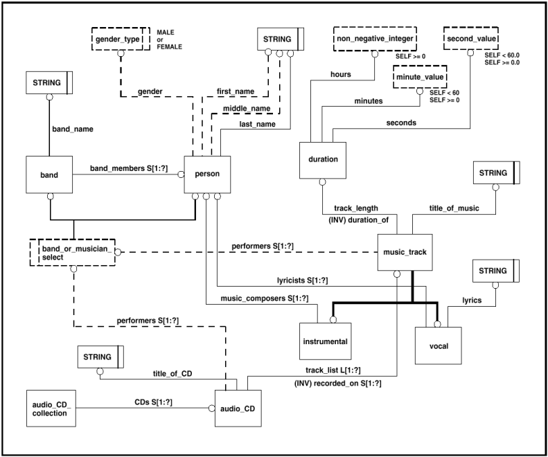
EXAMPLE — The duration_ofinverse attribute on the Duration entity in Fig. A.1 indicates that a Duration must be specified as the track_length of exactly one Music_track . This corresponds to the assertion that a duration can only exist if it is specified as the track length of a music track.
NOTE — Attributes and optional attributes may be aggregates. Types of aggregates defined in the EXPRESS language include arrays, bags, lists, and sets. Attributes that are arrays, bags, lists, or sets are denoted on EXPRESS-G diagrams by placing the letter“A,” “B,” “L,”or“S,” respectively, after the attribute name. The size of the aggregate is indicated on the diagram within square brackets that immediately follow the letter indicating the aggregate type.
EXAMPLE — In Fig. A.1 the track_list attribute on the Audio_CD entity specifies a list of one or more (the“?” indicates that the size of the list does not have an upper bound) Music_track s.
Optional Attribute Symbol: An optional attribute symbol [see Fig. A.2 (G)] represents a property of an entity that need not be specified.
Supertype/Subtype Symbol: A supertype/subtype symbol [see Fig. A.2 (H)] represents the relationship between an entity that is a supertype and the entity that is its subtype. The bubble is placed on the subtype entity.
NOTE — A subtype inherits all the attributes of its supertype(s).
EXAMPLE — The Instrumental entity in Fig. A.1 inherits the performers , recorded_on , title_of_music , and track_length attributes from the Music_track entity.
Simple Data Type Symbols: Simple data type symbols [see Fig. A.2 (E)] represent basic values. The kinds of simple data types that are defined in the EXPRESS language are INTEGER, REAL, STRING, NUMBER, BOOLEAN, LOGICAL, and BINARY. The kind of simple data type determines what values the simple data type may take on.
Select Data Type Symbol: A select data type symbol [see Fig. A.2 (D)] indicates that an attribute may be one of the several types specified by the select data type.
Enumerated Data Type Symbol: An enumerated data symbol [see Fig. A.2 (B)] indicates that values that an attribute may take on are limited to those values specified in an enumerated list.
NOTE — The values that enumerated data types are permitted to take on are documented in EXPRESS models. These values are not normally shown in EXPRESS-G diagrams. However, for readability, the permissible values for Gender_type in Fig. A.1 have been annotated to the EXPRESS-G diagram.
Defined Data Type Symbol: A defined data type symbol [see Fig. A.2 (C)] represents a value that is based on a simple data type. However, defined data types have additional semantics associated with them and may have additional constraints placed upon them that further limit the values they may take on.
NOTE — The constraints placed on defined types are documented in EXPRESS models. These constraints are not normally shown in EXPRESS-G diagrams. However, for readability, the constraints for the defined types in Fig. A.1 have been annotated to the EXPRESS-G diagram.
NOTE — For a more complete presentation of EXPRESS and EXPRESS-G see ISO 10303-11 [3].
STEP integrated generic resource constructs are useful in creating product data models as they define basic concepts and the relationships between those concepts that are relevant over many domains (e.g., the relationship between a property definition and a shape aspect). The underlying structure of the DSCDM is based on four entities from the STEP integrated generic resources. These entities are Shape_aspect , Shape_aspect_relationship , Property_definition , and Property_definition_relationship . The Shape_aspect , Shape_aspect_relationship , and Property_definition entities are from STEP Part 41 [11]. The Property_definition_relationship entity is from STEP Part 45 [12]. An abbreviated EXPRESS-G diagram of these entities is shown in Fig. B.1.
The definitions of the four entities shown in Fig. B.1 are provided in Tables B.1 – B.4. These definitions are taken from STEP Part 41 [11] and STEP Part 45 [12].
NOTE — The clause numbers specified within Tables B.1 – B.3 are from STEP Part 41 and should not be confused with the clause numbers of this paper.
NOTE — The clause number specified within Table B.4 is from STEP Part 45 and should not be confused with a clause number of this paper.
This appendix presents possible refinements to the DSCDM. These refinements are intended to represent possible ways in which the DSCDM may be further specialized. Depending on the application, the specializations may or may not be required. Furthermore, the specializations shown here are clearly not the only way in which the DSCDM might be specialized.
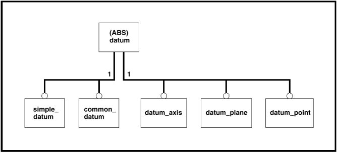
The Datum entity could be further refined to account for the different types of datum (i.e., datum points, datum axes, and datum planes). Figure C.1 is an EXPRESS-G diagram illustrating this specialization.
Typically, when one envisions the concept of feature, one visualizes a single surface of a part. However, features may be composed of other features. Subsequently, datum features may be composite datum features.
Furthermore, features may be constituents of other features. That is, a feature may constitute only a portion ofa larger feature. Subsequently, datum features may be constituent datum features.
EXAMPLE — The chain line in Fig. C.2 indicates that datum feature A is a constituent of the feature that is the bottom surface of the part.
In cases in which parent-child relationships need to be captured for composite and constituent datum features, the Datum_feature entity may be specialized, as shown in Fig. C.3.
NOTE — Figure C.3 does not show the various rules that would be associated with the entities introducedin this specialization.
EXAMPLE — A rule on the Composite_feature entity might correspond to the assertion that a composite feature shall not be composed of itself.
The Datum_target entity could be further specialized to account for the different types of datum targets (i.e., datum target points, datum target lines, and datum target areas). Additionally, the Datum_target entity might be further specialized to indicate when a datum target is a constituent of another feature. Figure C.3 is an EXPRESS-G diagram illustrating this specialization.
NOTE — Typically, datum targets are not“complete features;”typically, they are constituents of other features. However, there is no requirement that this be the case. Consequently, any specialization of the Datum_target entity should not require the Datum_target to be associated with a parent entity.
EXAMPLE — The datum targets shown in the technical drawing presented in Fig. C.4 are “complete features.”
This appendix discusses the difference between a datum reference frame and a datum system.
Though the concept of datum reference frame is not modeled in the DSCDM (as it is outside the scope of this paper), it is important to understand how a datum reference frame differs from a datum system. While both datum reference frames and datum systems consist of datums (and some datums may be simultaneously in both datum systems and datum reference frames), the constraints placed upon the datums of a datum reference frame differs from the constraints placed upon the datums of a datum system. That is, datums of a datum system have sequential constraints (i.e., datum precedence) placed upon them. By contrast, datums of a datum reference frame have positional constraints placed upon them (e.g., the datum planes of a datum reference frame are always mutually perpendicular).
In other words, a datum system specifies the order in which the datums are established within the datum system, and a datum reference frame specifies the positional relationship among the datums of the datum reference frame. Figure D.1 shows the inter-relationship among the datums of a datum reference frame.
EXAMPLE — In Fig. 10 there are two datum systems specified and only one datum reference frame. The first datum system contains datum plane A and datum axis B; and the second datum system only contains datum plane A. The datum reference frame contains datum plane A and datum axis B but it also contains the two datum planes labeled the“second and third planes of the datum reference frame.”Though not shown, the datum reference frame also contains a datum point at the intersection of the three datum planes and the two datum axes formed by the intersection of datum plane A with each of the other two datum planes.
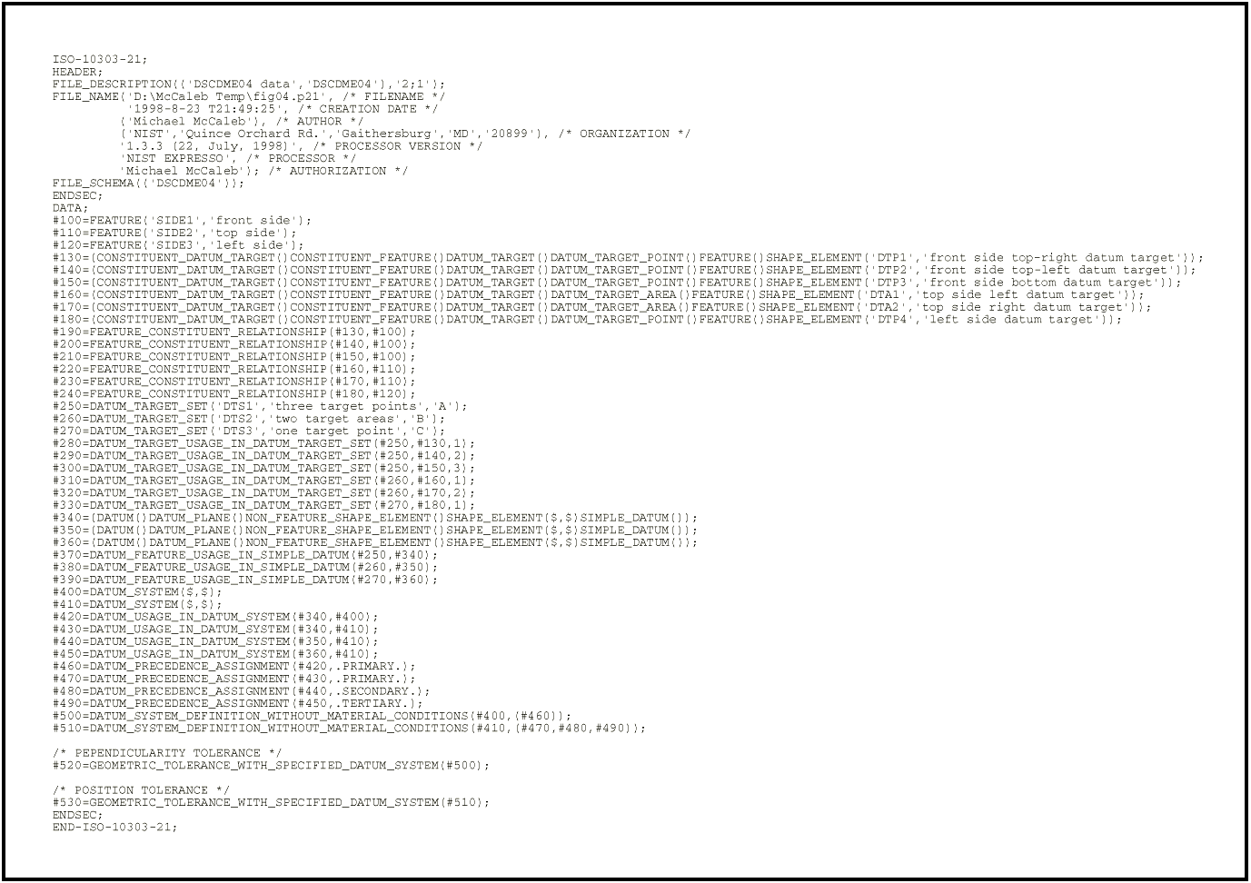
This appendix presents three data populations that correspond to the technical drawings in Fig. 4, Fig. 10, and Fig. 12. The model used for these data populations is presented in Fig E.1 and consists of the DSCDM and the specializations of the DSCDM presented in Appendix C. This model also includes a Shape_element entity,which corresponds to the generic concept of shape element. Additionally, a Non_feature_shape_element entity is included, which corresponds to any shape element that is not actually on the surface of a part. Types of Non_feature_shape_element s are Datum s and Datum_system s. The data populations presented in the tables below show how the DSCDM might be used to exchange data, and also provide a validity check on the data model. These data populations are presented in the format specified in STEP Part 21, ISO 10303-21 [16].
In order to interpret the data populations presented in
the tables below, it is necessary to know which values
correspond to which attributes. The order in which
attribute values occur within entity instances within
Part 21 files (files conforming to the format specified
in ISO 10303-21) follows the order in which the
attributes arespecified within entity declarations in the
corresponding EXPRESS model. However, as the actual
EXPRESS model has not been presented in this paper, Fig.
E.1 has been annotated to indicate the attribute order.
In cases inwhich an entity has multiple“forward
” attributes (inverse attribute values are not
explicitly specified in Part 21 files), an encircled
number (e.g.,  ) has been placed
after each of the attribute names to indicate the
attribute's order.
) has been placed
after each of the attribute names to indicate the
attribute's order.
EXAMPLE — In Fig. E.1, the  and
symbols associated with the used_datum and
comprised_datum_system attributes of the
Datum_usage_in_datum_system entity indicate that
in instances of the Datum_usage_in_datum_system
entity, within Part 21 files, the used_datum
attribute value would be first, followed by the
comprised_datum_system attribute value.
and
symbols associated with the used_datum and
comprised_datum_system attributes of the
Datum_usage_in_datum_system entity indicate that
in instances of the Datum_usage_in_datum_system
entity, within Part 21 files, the used_datum
attribute value would be first, followed by the
comprised_datum_system attribute value.
EXAMPLE — Entity instance#420 in Table E.1 is an instance of the Datum_usage_in_datum_system entity.In this entity instance the value 340 corresponds to the used_datum attribute and the value #400 corresponds to the comprised_datum_system attribute.
NOTE — In Part 21 files, values corresponding to inherited attributes are specified prior to values correspondingto non-inherited attributes.
EXAMPLE — Entity instance #140 in Table E.2 is an instance of the Datum_feature entity. In this entity instance the values `SIDE1', `right side', and `A' correspond to the name , description , and identification attributes, respectively. The name and description attributes are inherited from the Shape_element entity.
NOTE — The“$” character is used as a placeholder for optional attributes for which a value is not specified.
EXAMPLE — Entity instance #400 in Table E.1 is an instance of the Datum_system entity. The “$” characters in this entity instance are used to indicate that no values are specified for the optional name and description attributes that the Datum entity inherits from the Shape_element entity.
Figures from L. Foster, GEO-METRICS IIIm, (pages 260 & 265). 1994 Addison Wesley Longman Inc. Reprinted by permission of Addison Wesley Longman. ASME Y14.5M-1994 figures 4-1, 4-5, 4-14, 4-19, 4-20,4-22, 4-23 were reproduced with the permission of the American Society of Mechanical Engineers, ASME.Copyright remains with ASME. Figure 6-46 of Design Dimensioning and Tolerancing, Bruce A. Wilson, was reproduced with the permission of the Goodheart-Willcox Company, Inc. Copyright remains with Goodheart- Wilcox Company, Inc. Figure 42 taken from ISO 5459:1981; portions of clauses 2.4.4.2 and 2.4.4.4 and 2.4.4.5 taken from ISO 10303-41:1994; portions of clause 4.4.2 from ISO 10303-45:1998; and portions of clauses 4.4.1 to 4.4.5 and 6.4.4 taken from ISO 10303-47:1997 have been reproduced with the permission of the International Organization for Standardization, ISO. These standards can be obtained from the American National StandardsInstitute, ANSI,11 West 42nd Street, 13th floor, New York, N.Y. 10036, USA or directly from the Central Secretariat, ISO, Case postal 56, 1211 Geneva 20, Switzerland. Copyright remains with ISO. The author would like to thank Frederick Tolmie for the useful discussions concerning this research. Additionally, the author would like to thank Margaret Sheehan McCaleb for her invaluable editorial assistance.