
J. Weissmüller
Institut für Nanotechnology
Forschungszentrum Karlsruhe
76021 Karlsruhe, Germany and
Universität des Saarlandes
66041 Saarbrücken, Germany
R. D. McMichael
National Institute of Standards and Technology
Gaithersburg, MD 20899–0001, USA
A. Michels
Universität des Saarlandes
66041 Saarbrücken, Germany
R. D. Shull
National Institute of Standards and Technology
Gaithersburg, MD 20899–0001, USA
The paper presents a theoretical analysis of elastic magnetic small-angle neutron scattering (SANS) due to the nonuniform magnetic microstructure in nanocrystalline ferromagnets. The reaction of the magnetization to the magnetocrystalline and magnetoelastic anisotropy fields is derived using the theory of micromagnetics. In the limit where the scattering volume is a single magnetic domain, and the magnetization is nearly aligned with the direction of the magnetic field, closed form solutions are given for the differential scattering cross-section as a function of the scattering vector and of the magnetic field. These expressions involve an anisotropy field scattering function, that depends only on the Fourier components of the anisotropy field microstructure, not on the applied field, and a micromagnetic response function for SANS, that can be computed from tabulated values of the materials parameters saturation magnetization and exchange stiffness constant or spin wave stiffness constant. Based on these results, it is suggested that the anisotropy field scattering function SH can be extracted from experimental SANS data. A sum rule for SH suggests measurement of the volumetric mean square anisotropy field. When magneto-crystalline anisotropy is dominant, then a mean grain size or the grain size distribution may be determined by analysis of SH.
Keywords: exchange constant; magnetic anisotropy; magnetic microstructure; magnetism; micromagnetics; nanocrystalline materials; neutron scattering; small-angle neutron scattering; spin-wave stiffness. .
Accepted: April 14, 1999
Available in PDF for printing from the NIST Virtual Library. Go!
Nanocrystalline ferromagnets exhibit favorable soft [1,2] and hard magnetic [3,4,5] properties that are the subject of current research. In the simplest conceptual case, these materials can be single phase, single component polycrystalline solids with a grain size of the order of 10 nm, and with uniform values of the local magnetization magnitude and of the exchange stiffness constant. In this case, the nuclear microstructure affects the magnetization and, hence, magnetic properties such as coercivity and remanence, exclusively through the magnetic anisotropy. The nuclear microstructure determines the magnitude and the local orientation of the anisotropy field,that is the derivative of the magnetic anisotropy energy density with respect to the orientation of the magnetization, which acts as a torque on the magnetic moments, resulting in a nonuniform magnetic microstructure. Because of the importance of the anisotropy fields for the magnetic properties of nanocrystalline materials, it is of interest to characterize their magnitude and spatial arrangement, in other words the microstructure of the anisotropy fields. In this paper, we show how quantitative information on the anisotropy field microstructure can be obtained by combining small-angle neutron scattering (SANS) data with an analysis in terms of the theory of micromagnetics.
The magnetic domain structure of materials at low applied magnetic fields gives rise to neutron refraction [6] and to depolarization [7,8] of the transmitted neutron beam, and can be studied thereby, but of interest here is neutron scattering at sufficiently high applied fields where the scattering volume is essentially a single magnetic domain. In this case, magnetic SANS arises from small (static) variations, on the scale of a few nanometers to a few hundreds of nanometers, of the orientation of the magnetization vector about the direction of the applied field. The technique is therefore well suited for combination with micromagnetics theory [9,10,11], that describes the spatial variation of the magnetization, at equilibrium, in terms of a continuum approach which applies to length scales where the discrete atomic structure of matter can be neglected. In amorphous ferromagnets, inelastic SANS is an established technique for determining an important parameter of micromagnetics, the spin-wave stiffness constant [12,13]. Elastic SANS, that is of interest in the present context, has been shown to yield information on magnetic correlations in superparamagnetic nanocomposites [14], and on the ferromagnet-superparamagnet transition which occurs near the Curie temperature of one of the phases in multi-phase nanocrystalline ferromagnets [15]. In single-phase nanocrystalline ferromagnets, SANS indicates the presence of correlations in the magnetic structure on a length-scale larger than the grain size [16,17]. Studies of dislocation arrays in cold-worked ferromagnetic single crystals have demonstrated that a combination of SANS experiments with micromagnetics theory can provide information on the nuclear microstructure [18]. Preliminary results of the present study [19] indicated that SANS experiments on single-phase bulk nanocrystalline materials with low porosity, hence low nuclear scattering cross-section, are in good agreement with predictions from micromagnetics over a wide range of applied magnetic fields and scattering vectors.
Modeling remanence or coercivity of nanocrystalline materials by micromagnetics requires numerical computation [5]. But in the limit of nearly parallel alignment of all spins, at sufficiently high applied fields, there are closed form solutions for the magnetization [10,21] that are amenable to combination with scattering theory, and it is this approach that we shall explore. The paper is organized as follows: Sec. 2 discusses the micromagnetics solution for the Fourier components of the magnetization in terms of the applied magnetic field and of the Fourier components of the anisotropy field. Section 3 combines the results of micromagnetics with the theory of magnetic neutron scattering, and derives a result for the differential scattering cross-section in terms of the Fourier components of the anisotropy field and of a micromagnetics response function for SANS that depends on the applied field and on measurable magnetic materials constants. Section 4 is a derivation of expressions for averages of the scattering cross-section that apply to commonly used experimental scattering geometries and to materials with isotropic microstructure. Section 5 discusses an invariant of magnetic SANS, that relates to measurement of the magnitude of the anisotropy field. Section 6 deals specifically with the special case of nanocrystalline materials where the anisotropy field is exclusively from magnetocrystalline anisotropy. Section 6.1 discusses an approximate closed form solution for the magnetization in real space, both for a single grain and for a nanocrystalline material. Based on this solution, criteria are derived for the range of grain size and applied field to which the result of the previous sections apply. Section 6.2 presents results of the theory for SANS of nanocrystalline materials. Experimental results on nanocrystalline Ni and Co will be presented in a subsequent publication [20].

We aim to analyze the magnetic microstructure in a bulk nanocrystalline material, that is a space-filling array of nanometer-sized grains with different crystallographic orientations, restricting attention to situations where elements of the nuclear microstructure, such as grain boundaries or dislocations, do not affect the local values of the atomic magnetic moment and of the exchange stiffness constant. With this in mind, we consider the saturation magnetization MS = ρa µa and the exchange stiffness constant A to be uniform. The symbols ρa and µa denote the atomic density and the atomic magnetic moment, respectively. The inhomogeneous nuclear microstructure affects the magnetization because the combined effects of magnetocrystalline and magnetoelastic anisotropy determine the anisotropy energy density a that depends on position xand on the magnetization M, that is a = a[ x, M(x)]. The anisotropy energy enters the equations of micromagnetics theory through the anisotropy field (or perturbing field) HP(x), defined (in SI units, and with µ0 the magnetic constant, also called the permeability of vacuum) by

With M subject to |M| = MS, the vector HP is normal to M; in other words, the anisotropy field results in a torque on the magnetic moments, of nonuniform magnitude and direction, that deflects the magnetic moments from the perfectly aligned state.
At equilibrium, the static response of the magnetization to the magnetic field H and to the anisotropy field satisfies the micromagnetics equation (compare to Sec. 4.1 of Ref. 9):

for an orthonormal basis { ex, ey, ez}, where for any vector f the scalars fx , fy , fz, and f are, respectively, the Cartesian coordinates of f relative to { ex, ey, ez } and the modulus of f. The magnetostatic exchange length [5,23] lM is defined as

In the limit where the angle of misalignment of the
magnetic moments relative to the mean magnetization
 M
M is small, Eq. (2) can
be linearized [9] by neglecting terms that are of second
order in MP(x),
the component of the magnetization perpendicular to
 M
M ,
,

It has been shown [10,21] that, with the magnetization and the fields expressed in terms of their Fourier trans forms, the linearized equation can be solved indepen dently for each wavevector q. We find it useful to discuss the solution in terms of h (q), the Fourier transform of HP(x), and of m(q), the Fourier transform of MP(x) /MS:


By definition, HP depends not only on x but also on M and, hence, on the applied magnetic field. For instance, HP vanishes when the magnetization is aligned with one of the low energy (“easy”) directions of the crystal lattice. In the limit of small misalignment, changes of HP due to re-orientation of M result only in second order effects on the magnetization; therefore, the dependency of HPon M can be ignored.
We write the magnetic field H as the sum of
the applied field Ha and of the
demagnetizing field Hd, and
separate Hd into two components:
the field, Hds, which
arises from the discontinuity of M at the
macroscopic sample surface, and the field,
Hdb, which arises
from the divergence of M in the bulk.
Hds varies slowly
with position in the material and is here approximated by
the uniform field Hds
= – Nd  M
M , with the demagnetizing factor
Nd dependent on the sample geometry. It
is emphasized that, as a consequence of the uniformity of
MS and A, there is no a
priori discontinuity of M at internal
interfaces, therefore
Hds is exclusively
from the macroscopic external surface of the material,
and is entirely unrelated to the grain size or grain
shape. Grain shape enters the equations of micromagnetics
through HP(x), and
its effect on magnetic properties is therefore accounted
for in the solution for M(x
).
The bulk contribution to Hd is given by (compare Ref. 21)

it gives rise to a restoring force that tends to suppress variations of M with Fourier components m(q ) parallel q , thus stiffening the magnetic microstructure against such variations.
Solutions to Eq. (2) have been derived for several special cases, in particular for amorphous ferromagnets with random anisotropy (ignoring Hdb) [22], and for the case where HP(x) is due to magnetostriction in cubic single crystals, for instance in the strain field of a dislocation [10]. For the present case of a polycrystal, where a more general form of the magnetocrystalline anisotropy field is considered, it is readily verified by insertion that, in the limit of small misalignment, the solution is

The vector qz denotes the component of q that is normal to the applied field Ha, and θ is the angle between q and Ha. Heff denotes an effective field, defined by

Heff depends on the magnitude of the internal field Hi = Ha + Hds and on the exchange length of the internal field [23], lH, defined by

A simpler expression than Eq. (8) is relevant for the most commonly used geometry for SANS (compare Sec. 3 below). Consider the applied field and the mean magnetization along e z, hence the anisotropy field in the plane containing ex and ey. When the incident neutron wavevector k0 is along ex, perpendicular to Ha, then the scattering vector for elastic SANS is in the plane containing ey and ez. Therefore, only Fourier components of the magnetization with qx = 0 are probed with this SANS geometry. For these components, Eq. (8) simplifies to

The term that depends on θ in Eq. (11) originates from the demagnetizing field from divergence of M in bulk, Hdb. At high applied fields this term is small compared to Heff, so that the Fourier coefficient m(q) of the magnetization is essentially the product of the Fourier coefficient h(q ) of the anisotropy field and of the reciprocal of the effective field. Because of the convolution theorem, the product in reciprocal space corresponds in real space to a convolution with the Fourier transform of 1/Heff, which is a decaying exponential with a characteristic length lH. The central implication of the result, Eqs. (8)-(10), is therefore that, within the assumptions of uniformity and linearity, the magnetic microstructure is the convolution of the anisotropy field microstructure with an exponential response function with a characteristic length lH that varies as the reciprocal root of the internal field.
For the purpose of illustration, we shall repeatedly refer to the example of Ni. We denote by µB, D, and g the Bohr magneton, spin-wave stiffness, and g-factor, respectively, and use the following values for Ni: MS = 528 kA/m (528 G) [24], µa = 0.6155 µB [25], ρa = 9.14×10 28 m– 3, D= 6.41×10– 40 Jm2 (400 meV Å2 ) [26, 27], g= 2.21 [28]. With Eq. (3) and the relation [29]

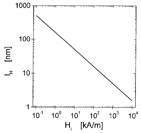
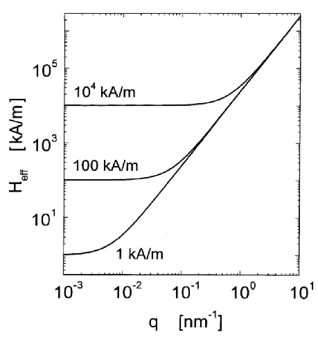
these parameters suggest lM = 6.9 nm for the magnetostatic exchange length in Ni. This value is comparable to experimental grain sizes. In Fig. 1, the value of the exchange length of the internal field, lH, in Ni, is plotted as a function of Hi for a typically accessible field interval in a SANS experiment. It is seen that for fields between 1 kA/m and 104 kA/m the exchange length varies between about 500 nm and 2 nm. Thus, the interval of exchange lengths is comparable to the interval of length scales that is accessible to measurement by SANS. At low fields lH is larger than typical grain sizes in nanocrystalline materials, which are of the order of 10 nm, but at the higher end of the field interval lHis smaller than the grain size. The effective field for Ni is plotted in Fig. 2 as a function of the magnitude of the wavevector q, and of the internal field Hi. It is seen that Heff is always large at high q, irrespective of the magnetic field. By Eq. (8), this implies that the high-q Fourier components of the magnetization are small, in other words sharp variations in M are suppressed by the effective field. Increasing Hi has a significant effect on Heff only at low q. Therefore only the low-q Fourier components of the magnetization are suppressed when Hi is increased, and the long-range variations in M are reduced. An explicit solution for the spatial variation of M for a special case is presented in Sec. 6.1 below.
For use in discussion of neutron scattering in Sec. 3, it is of interest to compute |m|2. With Eq. (8), this is found to be
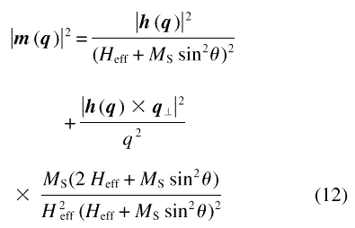
for arbitrary orientation of q. We find it convenient to express the vector h in terms of the scalar anisotropy field amplitude h(q) = h(q) and of a suitable variable for the orientation of h. In the following, Hi and M will be considered along ez, so that Hp and, hence, h, are confined in the plane containing ex and ey. The orientation of h can then be specified by the angle, ψ, included by h and ex. In terms of these quantities, Eq. (12) is

In other words, |m(q )|2 is proportional to the magnitude square of the anisotropy field and to a scalar function F that depends on the vector q and (through the effective field) on the vector Hi, as well as on their orientations relative to h(q ).

In this section, we derive a general equation for elastic SANS by micromagnetics structures that describes the differential scattering cross-section as the product of two functions: one dependent on the anisotropy field microstructure alone, and thus independent of the applied magnetic field, and a second that accounts for the field dependent response of the magnetization to the anisotropy field.
The macroscopic differential scattering cross-section (per volume) for elastic magnetic scattering at scattering vector k, due to an arrangement of atoms with positions xj, occupying a total volume of V , is the square of the magnitude of the sum of the atomic scattering amplitudes, including phase-shifts that depend on the orientation of the moments and on the atomic position [6, 31-33]:

Here, bmag denotes the magnetic scattering length of a single atom with magnetic moment µa, and the vector Q is related to a unit vector ε in the direction of k and to the atomic magnetic moment by the vector function

which is alternatively and equivalently expressed by the Halpern-Johnson tensor [31].
It is well known that the discreteness of the atomic structure of matter is of no importance for small-angle scattering. Therefore, the sum in Eq. (14) can be replaced by an integral involving the magnetization and the phase factor; this leads to an expression for the differential scattering cross-section in terms of the Fourier transform of the magnetization [33]. It is also well known that adding an arbitrary constant to all the vectors Q leaves the scattering cross-section invariant, except for additional forward scattering which is not relevant to experiment. Since Q is a linear vector function of the magnetization, replacing µa/µa in Eq. (15), or the equivalent continuous function M(x)/MS, by the reduced perpendicular component of the magnetization MP(x)/M S amounts to such a change of Q by an additive constant vector. Since MP(x)/M S is the Fourier transform of m(q) [compare to Eq. (6)], evaluation of the integral equivalent to Eq. (14) leads to

where ρa is assumed to be uniform, and p(k) is defined by

Eq. (17) implies |p(k )|2 = |m(k )|2 sin2 α, with α the angle included by m and k. Equation (16) is therefore formally identical to well known results for magnetic neutron scattering (e.g., Ref. 33), except that it expresses the scattering cross-section in terms of the Fourier transform of MP instead of M.
When the magnetization obeys the linearized micromagnetics solution of the previous section, then Eq. (13) implies that the expression for the differential scattering cross-section, Eq. (16), can be re-written as the product of an anisotropy field scattering function SH(k), that depends only on the anisotropy field, hence on the nuclear microstructure, but not on the applied field, and of a micromagnetic response function for SANS, R(ψ, k, Hi), that depends on the applied field and on the scattering vector, as well as on the relative orientations of these quantities, but not on the geometry of the microstructure:

It is convenient to define SH and
R so that R is a dimensionless function,
and so that SH has the same units as
d mag/dΩ:


Besides making R dimensionless, the inclusion of terms MS2 in the definitions of both SH and R has the additional benefit of making SH, which is related to the anisotropy field, not to the magnetization, actually independent of the atomic magnetic moment. This follows since, by definition, MS = µa ρa, and since bmag = 0.27×10⁻¹⁴ m f µa/µB, where f denotes a form factor with f = 1 in the small-angle scattering region [6]. The anisotropy field scattering function is therefore, equivalently to Eq. (19), expressed in terms of the constant bH which does not depend on the material:


In SI units, bH = 2.9×10⁸ A–1 m–1 (in cgs units bH = 2.3×10¹⁰ Oe –1 m– 2 ).
Equations (18)-(22) are central results of this work. Within the limits of applicability of the linearized micromagnetics equation, hence of the results of Sec. 2, they imply that the field-dependent magnetic scattering cross-section for neutrons depends on the microstructure through a single function, SH(k). When the saturation magnetization and exchange stiffness constant are known, then the response function can be computed, and the equations then allow the anisotropy field scatter ing function to be determined from experimental scattering data, thus enabling measurement of the anisotropy field microstructure.
The explicit general expression for R(ψ, k, Hi) in terms of the magnitudes and angles of the quantities involved is lengthy and not illuminating, and it is therefore preferred to display results for some special geometries and averages that are of experimental interest.

Two averages are often relevant to experiment: the first extends over the scattering intensities of several defects that are statistically uncorrelated, and the second is an azimuthal average of the intensity on the detector. In considering the first average, we assume that the Fourier coefficients of the anisotropy field can be expressed as

with the hj(q) originating from individual defects (e.g., grains). Attention is restricted to microstructures where the directions of the anisotropy fields of the individual defects are uncorrelated, so that terms hi(q) · hj(q) with i ≠ j take both signs with equal probability. Consequently, the expectation value for the sum over these terms vanishes, and

Because Eqs. (8) and (17) express m and p as linear vector functions of h and m, respectively, it follows also that

By comparing Eq. (25.2) with Eq. (16) for the differential scattering cross-section, it is readily verified that the contributions of the individual defects to the overall differential scattering cross-section are also additive:

with SH, j(k) = 8π3 V–1 b2H hj(k)2. For nanocrystalline solids, this additivity of the magnetic scattering associated with the individual grains contrasts with nuclear scattering, where interparticle interference is strong, to the point that a decomposition of the overall nuclear scattering cross-section into a sum over cross-sections of individual grains, similar to Eq. (26), would be meaningless [34].
For microstructures with a high number of defects in the total scattering volume the sum in Eq. (26) can be replaced by an integral over the orientation of the defects. This is conveniently done in terms of a distribution function s(k, ψ), defined so that

the sum being over all defects with hl (q) oriented in the interval [ ψ– δψ/2, ψ+δψ/2].
The response function R has comparatively simple representations in terms of the magnitude and orientation of k when attention is restricted to two particular scattering geometries: the first has the incident neutron wavevector along ex, normal to the applied field, and hence has the scattering vector in the plane containing ey and the direction of the field, ez. In this geometry, the azimuthal angle φ under which the scattering is recorded on the two-dimensional detector coincides with the angle included by k and Ha, denoted above by θ. The second geometry has the incident neutron wavevector along ez, parallel to the applied field. For that geometry, we take φ measured relative to ex. With the response functions for the two scattering geometries denoted, respectively, by Rz(ψ , φ, k , Hi) and R|| (ψ , φ, k , Hi), one obtains
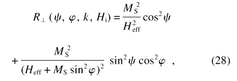

In terms of the quantities introduced by Eqs. (27)-(29), the overall differential scattering cross-section obeys

The integral has comparatively simple closed-form solutions when s is isotropic with respect to ψ, that is, when s(k, ψ) = SH(k)/2π :

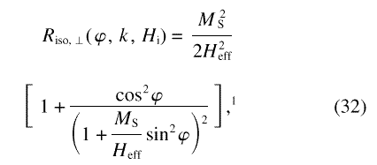

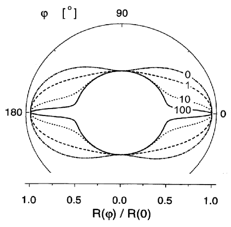
Consistent with the symmetry of the arrangement, the
scattering pattern has azimuthal isotropy when the field
is parallel to the neutron beam [Eq. (33)], but when the
field is normal to the beam [Eq. (32)] then the
scattering can be highly anisotropic, with the detailed
nature of the anisotropy dependent on the value of the
parameter p = MS/Heff and,
hence, on k and Ha. The polar
plot of Riso for that geometry, Fig. 3,
illustrates the anisotropy for different values of
p. It is immediately obvious that, at all fields,
the dependency of d mag/dΩ on
azimuthal angle is quite different from the well known
sin 2 φ variation that is observed
for a magnetically aligned array of isolated particles in
a nonmagnetic matrix, or for an array of pores in a
saturated ferromagnetic matrix. The azimuthal anisotropy
of d
 mag/dΩ in Fig. 3
at large effective field (small p) is readily
rationalized in terms of a distribution of
m(k ) that is isotropic in the plane
normal to Ha. At smaller field
(large p), the scattering cross-section is seen to
develop a “spike” in the direction parallel
to the field that is explained as follows: for the limit
where MS »
Heff, Eq. (8) shows that
m(k ) can have a significant
magnitude only in the direction where
mzk. The suppression of
components of m parallel to k
is a consequence of the demagnetizing field from
divergence of the magnetization [compare to Eq. (7)].
Besides mzk, m needs
also to satisfy mzHa, and for a
general orientation of k in the
plane normal to k0, that
contains Ha, the two conditions
for the orientation of m can only be
satisfied simultaneously when m takes one
of two discrete orientations, namely, m
parallel or antiparallel to k0.
Scattering from these Fourier components with
m||k0 leads to the
circular part of d
 mag/dΩ in the
polar plot for large p. But for the special
orientation where
k||Ha, all
orientations of m in the plane normal to
Ha satisfy
mzk, and can therefore
have significant values. For this orientation of the
scattering vector, d
 mag/d
Ω is therefore not only from two
orientations of m, but from the full
angular spectrum; hence the spike of higher intensity.
In addition to the average over the orientations of the
anisotropy field, one is often interested in the
azimuthal average of the scattering cross-section,
d mag/d(k)/dΩ =
(2π)–1 ∫
2π0d
 mag(k)/dΩ
dφ. The asymmetry of the microstructure is
further restricted by considering only cases where
SHdepends only on the magnitude of
k , not on φ. This applies,
e.g., to untextured polycrystals with equiaxed grains or
with elongated grains with isotropic orientation
distribution of the long axes. Integration of Eqs.
(31)-(33) for the isotropic case then yield


Figure 4 displays the response functions
Riso, z(k, Hi) and
 iso, ||(k, Hi) at
different applied fields, for the example of Ni.
 iso,
z(k,
Hi), (solid lines); and for neutron beam
parallel to the field,
  iso,
||(k, Hi), (dotted lines), versus
scattering vector k. Values of magnetic
field Hi are indicated in the figure.
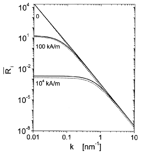
The results for the response function derived in this section can be combined with measured values for the magnetic field H i, with estimates for the demagnetizing field based on known sample shape, and with known values of the materials parameters, the exchange stiffness constant A and saturation magnetization MS to explicitly compute the response function. The anisotropy field scattering function can then be computed from experimental scattering data.

In studies of nuclear scattering, one can often obtain useful information from an invariant of nuclear scatter ing: the second moment of the radially averaged scatter ing intensity depends only on the root-mean-square of the variation in scattering length density, but not on the detailed geometry of the microstructure. Here, a similar expression is derived for the anisotropy field scattering function SH(q). The procedure is quite analogous to that applicable to nuclear scattering [35], and is outlined here merely to confirm its applicability to a vector function, the anisotropy field, as opposed to the scalar nuclear density.
The square of the magnitude of the anisotropy field Fourier coefficient |h(q )|2 is related to Hp(x) in real space by

The right-hand side of this equation can be expressed in terms of the Fourier transform of the Patterson or auto correlation function [35,36] C(r) of the anisotropy field:


The back transform of Eq. (38) is

When |h(q)|2 is
isotropic in the sense that it depends only on the
magnitude of q , then evaluation of Eqs.
(39) and (40) at r = 0 leads to a relation
for the mean square anisotropy field  |HP(x)|
2
 V , defined by

in terms of the measurable function SH(q):

The integrals in that equation are invariants of magnetic scattering that depend only on the mean square anisotropy field but not on the applied field or on the details of the microstructure.


In this section we derive a solution for the magnetization in real space in a nanocrystalline material with spherical grains. Based on this solution, criteria are derived for the minimum applied field necessary to warrant the validity of the small misalignment approximation, that is, for MP/MS « 1.
Consider a single-phase, single component nanocrystalline material where the crystallites have random crystallographic orientation, and where the anisotropy field arises from the magnetocrystalline anisotropy alone. Because each grain “j” is a single crystal, the anisotropy field in the grain is a constant vector, HP, j; between any pair of grains there is a random jump in the direction of the anisotropy field. Since the directions of the HP, j are uncorrelated, h(q) obeys Eq. (24), that is, the mean-square anisotropy field amplitude of the microstructure is a weighted sum of the mean-square anisotropy field amplitudes of the individual grains. The computation of |h(q)|2 for an arbitrary arrangement of grains is therefore straightforward once the solution for the single grain case is known. Therefore, we shall proceed to derive an expression for the anisotropy field amplitude of a single grain, assuming the most simple grain shape, the sphere.
For a sphere with radius  and constant
HP, the definition of
h(q) as the Fourier transform
of HP(x) suggests
that

with VS the volume of the sphere. Except for the pre-factors, Eq. (43) agrees with a well-known result in the theory of nuclear scattering [36].
For a single ferromagnetic spherical inclusion in a uniform ferromagnetic matrix where the anisotropy field vanishes everywhere outside of the inclusion, the Fourier transform m(q) of the magnetization is obtained by inserting the result for hS(q) into Eq. (8). We could not find exact closed-form solutions for the magnetization in real space, that is, for the inverse Fourier transform of m(q). However, an approximate closed-form solution is obtained when the terms in Eq. (8) that are due to the demagnetizing field from divergence of M are neglected, so that m(q ) = h(q)/Heff. This approximation is valid when Heff » MS. At smaller Heff the results constitute upper bounds for the magnitudes of m and M P, because the demagnetizing field always reduces the magnitude of m. With the above assumption, the inverse Fourier transform of m (q) yields a magnetization that depends on position only through the scalar distance r from the center of the inclusion:
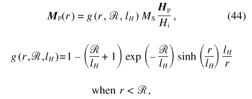

The function g describes the response of the
magnetization to the anisotropy field in the inclusion.
Figure 5 displays gfor different values of the
internal field, and for the example of an inclusion in Ni
with  = 5 nm, corresponding to a grain size of 10
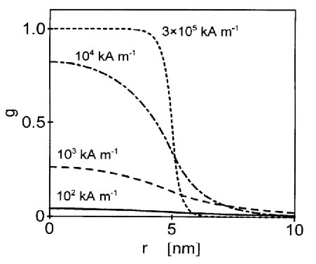
nm. It is seen that at high magnetic fields g
varies steeply at the interface between inclusion and
matrix; as the field is decreased, the variation at the
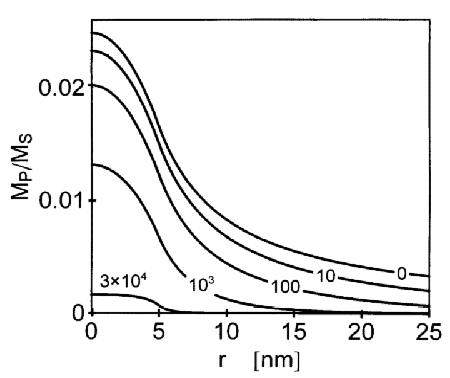
interface is smeared out. Figure 6 shows the magnitude of
the normal component of the magnetization
MP versus r. In Fig. 6,
Hp= 10– 2 T, and the
remaining parameters are the same as in Fig. 5.
Consistent with Fig. 5, it is seen that at high fields,
when lH, the variation of the
magnetization is confined to a narrow region near the
interface between inclusion and matrix, and that at lower
fields the magnetization varies in a transition region
which extends on a larger scale into the inclusion and
into the matrix.
Consider the case of small applied fields, where
lH> . In this case,
inspection of Eq. (44) shows that there is a
“slow” decrease of MP with
distance r from the center of the inclusion in the
region outside the inclusion where
  <
r< lH, with approximately
MP%1/r. A faster, approximately
exponential decrease is suggested by the same equation
for larger distances, r>lH.
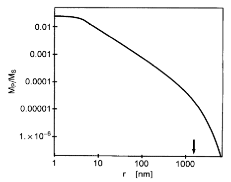
This is illustrated in the log-log plot of
MP versus r in Fig. 7, where the
1/r variation of MP leads to a
straight line for
  < r<
lH.The transition between slow and fast
decrease of MP at r ≈
lHsuggests that variations of
M are correlated on a length-scale of the
order of lH . Since
lH varies as the inverse root of the
applied field, this correlation length diverges when
Hi is reduced to zero (compare to Fig.
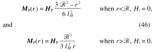
1). This is also seen from the limiting form of Eq. (44)
for Hi = 0, which has a 1/ r
variation of the normal component of M
everywhere outside the inclusion:
 = 5 nm in Ni, versus distance r from
the center of the inclusion. The numbers in the figure
indicate the value of the magnetic field
Hi.
 = 5 nm in an otherwise anisotropy field-free
matrix versus distance r from the center of the
inclusion. The numbers in the figure indicate the value
of the magnetic field Hi in units of
kA/m. Material parameters are for Ni.
 = 5 nm in Ni, at an internal field of
10–2 kA/m. The arrow indicates the
exchange length lH.
Equation (46) suggests that, in the case of a single
inclusion in an otherwise uniform matrix, the condition
Hp « 2 MS
l 2M / 2 is sufficient for the misalignment to be
small and the linearized theory to be applicable,
independent of the applied field. For Ni with a grain
size of 10 nm, this requires HP «
2000 kA/m, and compares to considerably smaller
expectation values for HP due to
magnetocrystalline anisotropy of about 3.7 kA/m at 300 K
and 74 kA/m at 4 K (compare to Sec. 6.2 below).
Let us now consider the validity of the small
misalignment approximation in the case of a
nanocrystalline material, that is, a material entirely
occupied by grains such as the one discussed above. At
internal fields sufficiently large that
lH «  (or, equivalently,
Hi » MS
lM2 /
 2),
the perpendicular magnetization decays exponentially
outside each grain, so that there is little overlap of
magnetization profiles from neighboring grains. However,
at small applied fields, lH, and hence
the range of the perturbations, are larger than the grain
size (lH »
  or,
equivalently, Hi «
MS
l2M /
  2). In this case, the net value of
the perpendicular magnetization at a given point is a
superposition of perturbations with random sign
originating from a large number of neighboring grains.
Therefore, even when MPdue to
the anisotropy field of each individual grain is small,
the expectation value for the net magnitude of
MP may be large. As a measure of
the mean net misalignment in the nanocrystalline material
we consider the volumetric mean square of
MP, defined by
  |MP|2
|MP|2 V
= V–1∫
|MP|2 dV, with the
integral extending over the entire volume of the
material. Considerations analogous to those leading to
Eq. (25) suggest that the contributions of individual
grains to the integral are additive, so that
  |MP|2
|MP|2 V=
V–1
 j|
MP
j(r)|2 4 π
r2dr, the summation being over the individual
magnetization profiles of all grains. With Eq. (44) for
MP, this leads to
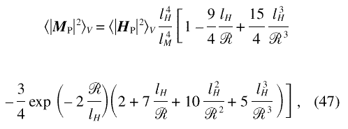
and to the limiting forms
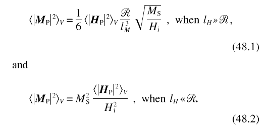
Expressing the requirement of small misalignment,
somewhat arbitrarily, as  |MP|2
|MP|2 V
/ MS2< 0.01, it is found
from these results that small misalignment requires
Hi> 300
  |HP(x)|
2
 V2
MS–3 (
 /lM) 6 when
lH »
  , and
Hi>10
  |HP(x)|
2
 V 1/2 when
lH «
  . For the example of
Ni with a grain size of 10 nm and HP =
50 kA/m, the two conditions are
Hi>1.9 kA/m and
Hi>500 kA/m, respectively. The
second condition is automatically satisfied since, by Eq.
(10), H<
  implies
Hi >1000 kA/m. In conjunction with
the first condition this implies that, for the example,
the small misalignment approximation remains valid down
to quite small applied fields.
Since the magnitude of the mean (macroscopic) magnetization in the model is approximately

Eq. (47) has an immediate relation to the approach to saturation in a magnetization isotherm. Results for the magnetization of amorphous ferromagnets with random anisotropy are formally similar to the expression for the mean magnetization implied by Eq. (47), and compare favorably to experimental magnetization isotherms of nanocrystalline ferromagnets [22, 37, 38]. A discussion with relation to experimental magnetization data for nanocrystalline Ni and Co will be given in a subsequent publication [20].

As above, we consider a nanocrystalline material with magnetocrystalline anisotropy only, and with random crystallographic orientations of the grains. The scattering cross-section will then depend on the mean-square anisotropy field and on the grain size or the distribution of sizes. Because of the random orientation, the expectation value for |HP|2 in a grain is independent of the grain size, and is identical to the value of the volumetric mean-square anisotropy field. The expectation value is obtained by computing HP in a single crystal as a function of the orientation of the magnetization relative to the crystal lattice, and averaging |HP|2over all orientations:

where Ω denotes the solid angle. |HP|2
|HP|2 Ωis a materials
constant, and is independent of grain size and grain
shape. Using the values for the magnetocrystalline an
isotropy constants in Refs. [39, 40], one finds that for
Ni
  |HP|2
|HP|2 Ω1/2 = 74 kA/m at 4 K
and
  |HP|2
|HP|2 Ω1/2 = 3.7
kA/m at 300 K.
The distribution of grain sizes is described by the
function n( ), defined so that
the number of grains with radius in the interval
[
 ,
,  +d
+d  ] is
n (
 )d
)d  . In analogy to
nuclear scattering by noninterfering particles, the
anisotropy field scattering function is an integral over
the scattering cross-sections of the individual grains,
weighted by the grain-size distribution function. For
spherical grains with random crystallographic
orientations, Eqs. (20) and (43) suggest that the
anisotropy field scattering function is then

Except for the prefactors, Eq. (50) is identical to the
nuclear interference function of an array of
noninterfering particles, and general asymptotic results
at small and large k are therefore immediately
transferable. In particular, the Guinier approximation
[35, 36] links SH(k) at small
k to a mean grain radius  H according to
SH(k)% exp (–
  H2
k2/3); and the asymptotic variation of
SH(k) at large k
satisfies the Porod approximation [41] with

where A denotes the total grain boundary area.
Note that information on the nuclear microstructure is
here obtained by analysis of
SH(k); since the differential
scattering cross-section depends on the product of
SH(k) and the micromagnetics
response function R, it is not permissible to
derive information on the nuclear microstructure by
analyzing d mag/dΩ
immediately in terms of the Guinier or Porod
approximations. In fact, the asymptotic variation of
d
 mag/dΩat high
k is readily seen to by quite different from the
k– 4 law: at high k, the
effective field Heff increases as
k2, and hence the response functions
vary asymptotically as k– 4. In
conjunction with the k– 4
variation of SH(k), this gives
rise to d
 mag/dΩ
%
k–8, which is a much steeper
dependency than the d
 mag/dΩ % k–4 intensity
variation that is expected for nuclear scattering from
microstructures with sharp interfaces. The high power-law
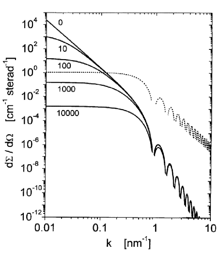
exponent at large k can be seen in Fig. 8, which
shows plots of d
 mag/dΩ at
different magnetic fields for Ni with a monodisperse
grain size of 10 nm and with
  |HP|2
|HP|2 Ω 1/2 = 50 kA/m.
 mag/dΩ for
nanocrystalline Ni with spherical grains of radius = 5 nm
and with
  |HP|2
|HP|2 Ω1/2 = 50
kA/m, plotted versus scattering vector k
for parallel geometry. The numbers indicate values of the
magnetic field Hi in kA/m. Dotted line:
anisotropy field scattering function
SH.
The Guinier radius obtained by analysis of
d mag/dΩ depends
both on the anisotropy field microstructure and on the
applied field. A series expansion of Eq. (36) about
k = 0 yields
  i
% 1 –
lH2 k2 at
small k, which implies the asymptotic form d
 mag/dΩ % exp[– (
 H2/3 +
lH2 ) k2].
Unless Hi « MS,
the same result is obtained with Eq. (35). Therefore,
independent of the scattering geometry, a Guinier fit to
d
 mag/dΩ yields a
field- dependent effective Guinier radius that obeys

In conjunction with this result, experimental investiga
tion of the field-dependence of  eff
may provide a means for measuring the exchange constant
A.

In summary, we have presented an analysis of small-angle neutron scattering by nanocrystalline ferromagnets that is based on an analysis of the magnetic microstructure in terms of the theory of micromagnetics. The analysis requires small misalignment of the magnetic moments and uniform magnitude of magnetization and exchange interaction; it applies irrespective of the nature of the magnetic anisotropy. Our results for the variation of the differential scattering cross-section with the applied field suggest that SANS experiments carried out at different fields allow the measurement of the anisotropy field scattering function. This function contains information on the magnitude of the anisotropy field and on the length scales over which it is correlated. Because the coefficients of magnetocrystalline and magnetoelastic anisotropy vary independently with temperature, comparison of anisotropy field scattering functions measured at different temperatures can also lead to insight into the nature of the anisotropy.
In experimental studies, the nuclear density and/or
composition will generally be nonuniform, and
consequently there can be a nonuniformity in the
magnetization, even at the highest fields when all spins
are aligned. The nuclear scattering cross-section is
independent of the applied field and the same holds true,
in the limit of small misalignment (small
MP), for the magnetic scattering
due to nonuniform saturation magnetization. This combined
nuclear and magnetic residual scattering
cross-section d residual/dΩ is not
accounted for in our micromagnetics approach. When the
arrangement of the elements of the nuclear microstructure
that give rise to residual scattering is uncorrelated
with the arrangement of elements that are responsible for
the anisotropy field microstructure, then the two
scattering cross-sections are additive, so that the
total differential scattering cross-section
d
 total /dΩ is

Therefore, when the response function is known,
measurement of the total scattering cross-section at two
different applied fields is required to compute the two
unknown functions d residual(k)/d
Ω and SH(k).
Note that the azimuthal anisotropy of the residual
scattering cross-section is in general quite different
from that of d
 mag/dΩ. For
instance, an isotropic microstructure subject to an
applied field orthogonal to the incident beam has
d
 residual /dΩ
%
[b2nuc + b2
mag sin2(φ)], where
bnucdenotes the atomic nuclear
scattering length, whereas d
 residual/dΩ obeys
the quite different dependence on azimuthal angle
expressed by Eq. (32).
In addition to their different dependency on the applied
magnetic field and on the azimuthal angle, the two
contributions to the total scattering cross-section also
depend in a different way on change of the neutron
polarization state. In residual scattering there is
interference between magnetic and nuclear scattering
amplitudes; such interference implies that the magnitude
of the scattering cross-section will depend on the
neutron polarization state [6, 33]. By contrast, there is
no interference between the nuclear scattering and the
scattering from micromagnetics structures in our model,
and consequently d mag/dΩ is
invariant with respect to a change of polarization.
Experimental studies with polarized neutrons may
therefore provide a verification of the separation of
residual from micromagnetics scattering.
Spin waves do not give rise to elastic scattering,
since the cross-section for elastic scattering depends on
the time average of the time-dependent correlation
function. But in general SANS instrumentation does not
completely discriminate inelastic scattering;
therefore, experimental SANS data may contain
contributions due to inelastic scattering from spin waves
[42]. With a magnon dispersion relation  ω = D k2+g
µB µ0
Hi, and an incident neutron of
wavevector k0, mass
mn, and energy
  ω =
ω =
 2
k02/(2
mn), the balances of energy and
momentum for the inelastic scattering event can only be
satisfied simultaneously when

This relation imposes upper and lower limits for the
allowed range of scattering vectors kfor inelastic
SANS from spin waves, and implies that this range narrows
as the magnetic field Hi is increased.
With 2 mn D/ 2
» 1 for most elemental ferromagnets (the value for
Ni is 193) , the term ±1 (where + or – refer
to the generation or annihilation of a magnon,
respectively) may be neglected, and it follows that spin
wave scattering is completely suppressed when the applied
magnetic field satisfies

For Ni and an incident neutron wavelength of 0.6 nm, this
requires Hi  73 kA/m (920 Oe).
Correction of the scattering data for signal from
inelastic scattering may be required at smaller magnetic
fields.
Our results imply that information on the anisotropy field microstructure may be obtained by analyzing the experimental anisotropy field scattering function: the value of the volumetric mean square anisotropy field can be measured, as can the total grain boundary area per volume and a mean grain radius, in case the magnetic anisotropy is dominated by magnetocrystalline anisotropy. In principle, the anisotropy field scattering function can also be analyzed in terms of a grain size distribution function, quite analogous to the analysis of nuclear scattering data by non-interfering particles. This is of relevance because a similar analysis is not possible for nuclear scattering by bulk nanocrystalline solids [34]. Thus, magnetic SANS may contribute to the characterization of the nuclear microstructure of nanocrystalline solids.
Because of the restrictive assumption of small misalignment, our discussion cannot provide an adequate analysis of the magnetic domain structure that develops at small applied magnetic fields. When the domain size is much larger than the characteristic size of coherent magnetic fluctuations, then it may be expected that the magnetic microstructure inside each domain may still be adequately described by the linearized theory. Also, the theory of micromagnetics applies to the structure of the domain walls, and the dependency of wall width on the grain size has been discussed in the literature [1]. Domain walls contribute to SANS at small applied field, but the magnitude of the signal depends on the wall area per volume, and there fore on the a priori unknown domain size. Hence, it is not immediately obvious how the effect of magnetic domains on SANS can be quantified. Previous experimental studies of SANS from nanocrystalline Fe and Ni have inferred a magnetic domain size by analyzing the data in terms of scattering by noninterfering, uniformly magnetized domains [16, 43]. Our results do not sup port such analysis, since they suggest that the magnetization inside the domains is highly nonuniform. In other words, there is strong scattering due to a super-position of uncorrelated and overlapping perturbations of the magnetization that decorate the anisotropy field microstructure; this scattering is on top of scattering by the magnetic domain structure. The magnetic scattering cross-sections of the individual perturbations can be additive, but their functional form (which depends on the applied magnetic field) is quite different from scattering by uniformly magnetized domains.
Contrary to our assumption of uniform exchange stiffness constant, the magnetic interactions in the core of defects in real materials may differ from those in the bulk. For instance the exchange coupling across grain boundaries may be weakened relative to the bulk, suggesting a jump of the magnetization vector across grain boundaries. The correspondingly larger Fourier components of the magnetization at high wavevector would lead to measurable deviations of the experimental scattering cross-section at high scattering vector from the predictions in the present work. Therefore, experiment may provide a test of the validity of the assumption of uniform exchange stiffness constant.
In subsequent publications [20], we shall present experimental SANS data for electrodeposited nano-crystalline Ni and Co that show good agreement with the predictions of this paper.

Helpful discussions with J. Barker and support by the Alexander von Humboldt Foundation (Feodor Lynen program) and by the Deutsche Forschungsgemeinschaft (SFB 277 and Heisenberg program) are gratefully acknowledged.

 jcos (k ·
δj)] for long wavelength
magnons. J is the exchange integral, athe
lattice constant, c' has the values 1, 2, 4, 2
√2 for sc, bcc, fcc, and hcp, respectively [23],
and the sum is over the z nearest neighbors at
positions δj relative to the
central atom.

About the Authors: Jörg Weissmüller worked as a visiting scientist in the Metallurgy Division of the NIST Materials Science and Engineering Laboratory in 1994-96; he is now a materials scientist at Institut für Nanotechnologie, Forschungszentrum Karlsruhe, and in the Technical Physics Department at Universität des Saarlandes. Robert D. McMichael and Robert D. Shull are materials scientists in the Magnetic Materials Group of the NIST Metallurgy Division. Andreas Michels is a Ph. D. student in the Technical Physics Department at Universität des Saarlandes. The National Institute of Standards and Technology is an agency of the Technology Administration, U.S. Department of Commerce.